


MatterBeam
-
Posts
1,570 -
Joined
-
Last visited
Content Type
Profiles
Forums
Developer Articles
KSP2 Release Notes
Bug Reports
Posts posted by MatterBeam
-
-
On 8/31/2019 at 11:47 PM, goldenpeach said:
Congratulation @MatterBeam! You have been awarded Thread of the Month for this very interesting post!
Thank you very much!

-
17 hours ago, DDE said:
Can actively cooled spacecraft armour replace the high-temperature radiator array?
Not really...
Spacecraft hulls don't have much surface area and they have to run cooler than whatever they're cooling, plus there's thermal conductivity problems with getting heat through an armor layer thick enough to be good armor.
Actively cooled armor works because heat comes and stays on the surface, and the only temperature limitation is the vaporization temp of the armor material...
But, nothing says you can't make use of your armor as a temporary heatsink, or a boost to cooling capacity if your radiator fins are damaged or forced to retract! Your power output would be severely crippled though.
-
4 hours ago, Shpaget said:
Regarding day night cycle of the moons, the long day or night would happen during the parts of the Uranus orbit when the Sun is normal to the moon orbital plane. When the Sun is in the orbital plane (one quarter of the orbit later), the day night cycle would coincide with orbital period, with daily solar eclipses.
How would that impact human circadian rhythm?
All structures will have to be underground to protect against cosmic rays, and it is generally safer. This means artificial lighting almost all of the time. Even if you went to the surface and sat in a glass bubble, you will find it rather dim. There is 370 times less sunlight.
-
51 minutes ago, sh1pman said:
You sure about this part?
https://www.space.com/28827-living-on-uranus-moons-titania-miranda.html:
"This means that during the planet's 84-Earth-year-long trip around the sun, the poles of Uranus and its moons experience 42 years of sunlight followed by 42 years of darkness."
-
38 minutes ago, YNM said:
Given the similarities between the two gas giants and two ice giants, which one of the four is more likely, given their respective location, size and feature, to harbour a colony in it's vicinity ? Like, I guess they'd scale up-and-down with each other, and as such you'd almost have a relative maximum ?
I would say Saturn is the most likely spot for serious colonization. It has the most interesting moons and a radiation environment more benign than even our Earth's.
-
Hi all. The original post is here: http://toughsf.blogspot.com/2019/08/how-to-live-on-other-planets-uranus.html
How to Live on Other Planets: Uranus
The weirdest of the planets. A blue giant, resting on its side.Could we find a home in the Uranian system?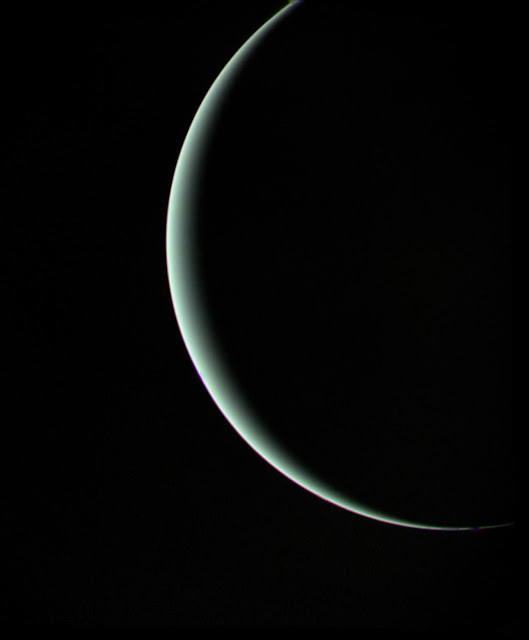 Uranus is the fourth-largest planet and the first ‘ice giant’. It orbits between 18.3 and 20.1 AU from the Sun, making it four times more distant than Jupiter and the furthest before Neptune.
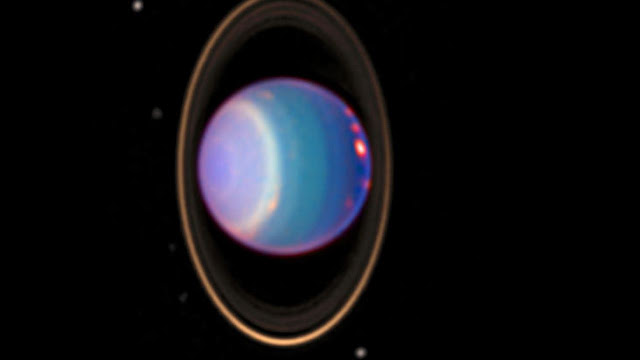
The most prominent features are the blue color derived from atmospheric methane and its axial tilt of 97.7 degrees. It also has a ‘surface’ gravity of 0.88g, the lowest of the gas giants, because it is just 14.5 times heavier than Earth.
Uranus is less well known than Jupiter or Saturn. We have less information to work with. What we can say is that it is a huge sphere of frozen methane, ammonia and water ices topped by hydrogen, helium and methane gases. It has a total diameter of 50,700km.Pressed between a solid core and thousands of kilometres of ices, we expect to find weird matter like ‘super-ionic water’ and ‘liquid diamond’.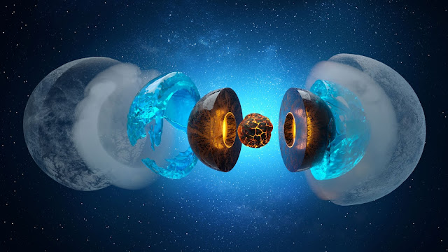
How could we live on this ice giant?
The pressures and temperatures deep inside Uranus are not survivable.Unless technologies for surviving those conditions are developed by the time we choose to settle the ice giant, we would be restricted to the upper layers of the atmosphere. It is the smallest and coldest atmosphere of all the planets in the Outer Solar System, so this zone is relatively close to the surface.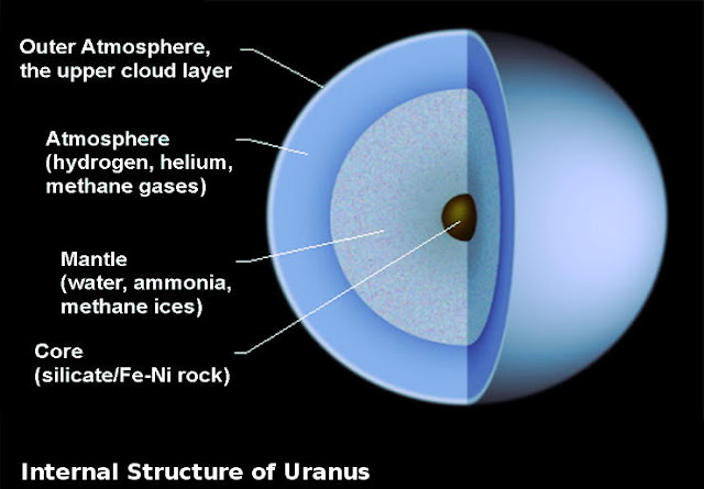
The ‘surface’ in this case follows the convention of being the altitude where ambient pressure is 1 bar. Temperatures in the 1 bar zone are about 76 Kelvin.The bottom of the atmosphere starts from a mild 320K but a pressure of 200 bars. Volatiles like methane, hydrogen sulphides and water condense into clouds.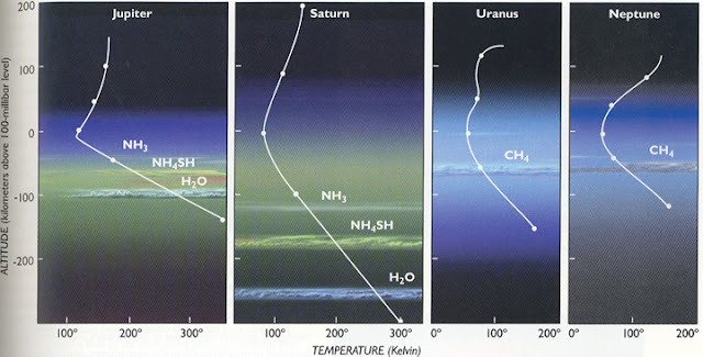 Going up, temperatures and pressures fall. The atmospheric composition changes with altitude.
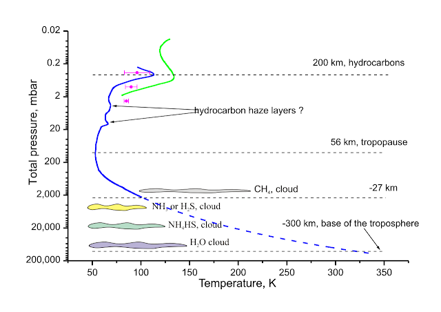
27 km below the 'surface', pressure is 2 bars and we still see methane clouds at <200K temperatures.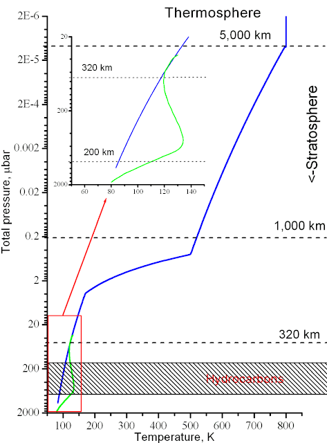
Overall, there is more helium than in other gas (15% by volume compared to 10% in Jupiter, 3.25% in Saturn) while the deuterium/hydrogen ratio is at 0.000055, which is better than Jupiter’s 0.000026 and Saturn’s 0.000017. The methane concentration is a respectable 2.3% as well. As you rise, gases other than helium and hydrogen become less present.
The lowest temperatures in the Solar System exist in Uranus’s atmosphere. It is measured at 50 Kelvin and it is currently unknown why the planetary core’s heat cannot escape to warm up the atmosphere like in other gas giants.
Cold does not mean calm.The winds in the Uranian atmosphere reach -100m/s at the equator and are strongest midway to the poles at +240m/s. These speeds are measured relative to the rotation of the planet (2590m/s at the equator). We don’t have any detail on the exact wind gradients between latitudes and altitudes.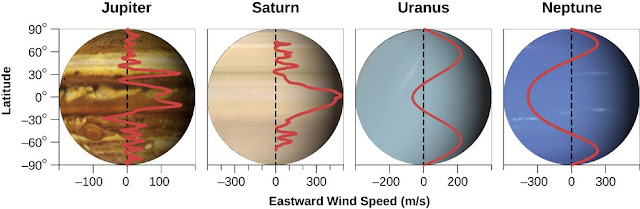 Uranus also has a ring system. Dust and ices orbit in bands extending from 38,000 to 98,000km above the center of the planet. Compared to other ring systems, there is less dust and more icy bodies in the 20cm to 20m size range.
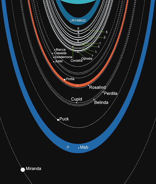
Within the rings are 27 moons.
Of the named moons are 13 irregular inner moons, too small to have the gravity to shape themselves in spheres and separate a crust from core. The innermost is Cordelia, 40km wide and orbiting at 49.8 thousand km. The largest of these is Puck, 163km wide and estimated to mass 2,900 trillion tons. It cannot be confirmed, but they are expected to resemble comets and be composed mostly of water ice and some dust.Five large, spherical moons follow. Miranda, Ariel, Umbriel, Titania and Oberon, named after Shakespearian characters like all the others, range from 471 to 1576km in diameter.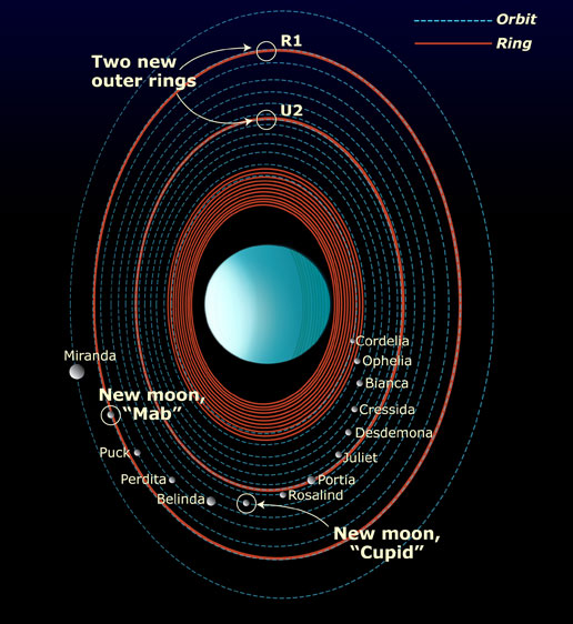 They have large solid cores and a thick layer of ice on top. All feature huge canyons, crevasses, cliffs and scarps. Tidal locking means they always face Uranus with the same side, and experience 42 years of continuous darkness followed by 42 years of uninterrupted sunlight. The icy surface is darkened by hydrocarbons.
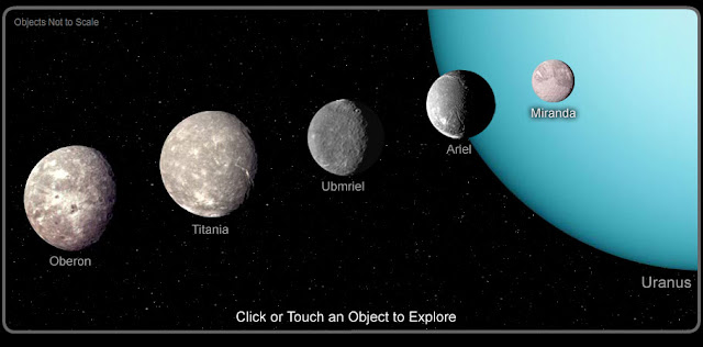 The outermost moons are a diverse group of a few dozen kilometres in diameter, sat in more or less inclined and eccentric orbits that are all retrograde (only small Margaret is not retrograde). Many are believed to be captured asteroids, such as Syncorax. As with the other small moons, they are low density mixes of ice and dust.
Most of these moons sit within the ice giant’s weird magnetosphere. It is weak, weaker than Earths’ by 25%, and the field lines don’t even pass through the center of the planet.Once every Uranian day, which is just over 17 hours, the magnetic field connects with the solar wind and allows a stream of protons to funnel down to strike the atmosphere. This could be the reason for the aurorae only recently observed.
In terms of radiation, Uranus is similar to Saturn. It is safer than Earth and far less dangerous than being near Jupiter.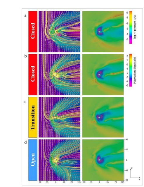
Uranuian magnetosphere's evolution
Habitability
Living within Uranus is a tough job.
On the upside, the gravity is not too different from Earth’s. The cold atmosphere makes floating with hot hydrogen somewhat easier than on Jupiter or Saturn; 1m^3 of pure hydrogen at 570K would lift 0.38kg if we take the density of the surrounding gas mix to be 0.42kg/m^3. Flying would be no more difficult than trying to maintain an altitude of 9,000m within our own atmosphere, so aircraft would look very similar to our own.
There is a definite need for insulation because of the low temperatures. Heat loss rates would be three times higher than on Earth.
Winds are high, but there is not much evidence of super-storms as on Jupiter and thus any floating or flying habitat should be able to be carried along by them. Some sources state that Uranus's weather system is 'featureless'.
The real concerns are resources, energy and viability.
Uranus is resource-poor. Access to hydrogen, helium and methane is readily available but not much can be done with them. Trying to obtain water would require diving to incredible pressures and is therefore impractical. Raw materials that are required to build or expand a habitat, such as metals and minerals, are simply unavailable.
Worse, Uranus is energy starved. Sunlight is a negligible 3.7 W/m^2. That’s 367 times less than what Earth receives! Any solar energy solution that might be practical at 1 AU from the Sun (perhaps 1kW/kg overall power density) would be worthless out at Uranus’s orbit of 20 AU (2.7W/kg). It would struggle to compete with RTGs at that level of performance.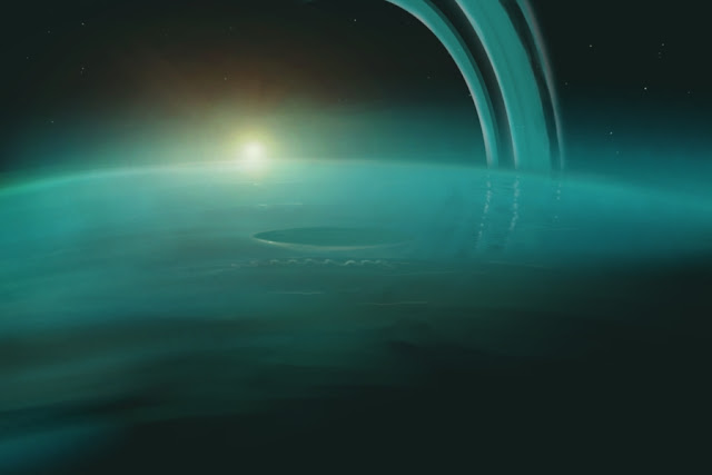
Art by SolidAhmad.
The winds could be used as was proposed for Saturn, but we do not have enough detail on the windspeed gradients to confirm whether this is practical. If the winds do not vary much between latitudes or altitudes, then the wind-wheels or wind-kites would have to be massive and might not even be able to float.
Nuclear energy is a reliable option as it does not depend on its environment. A permanent habitat would have trouble fuelling its reactors though. There is no accessible source of fissile fuel inside Uranus itself and the densities of the moons does not suggest that they have concentrations of any heavy elements near their surface or at a practical depth. All fissile fuel would have to be transported from the Inner Solar System.Fusion energy is the game-changer… but not in Uranus’s favour. Deuterium is the most abundant fusion fuel and we can extract it directly from our oceans or any icy body.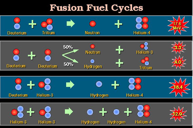 If Deuterium-Deuterium fusion is not yet accessible, then Tritium can be manufactured from lithium and any neutron source. Having engineered solutions at home is a simpler and more straightforward source of fuel than making multi-year round trips to the gas giants to extract Helium-3.
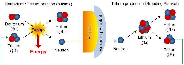
Helium-3 is admittedly the ‘cleanest’ of fusion reactions and it is attractive for use in propulsion and mobile applications, as significantly less neutron shielding is required around a Deuterium-Helium-3 reactor. However, even Helium-3 can be obtained from simply waiting for Tritium to decay. The half-life of Tritium is about 12 years, so large quantities can be produced from a Lithium to Tritium to Helium-3 production chain.
With that in mind, Uranus is the best planet to extract Helium-3 from. It requires much less deltaV to enter and exit the Uranium system than Jupiter or Saturn, and it is closer than Neptune.
However, the most apt answer to the ‘go to Uranus for Helium-3’ argument is an analogy using vanilla. Vanilla used to be a prized, rare extract from vanilla pods that had to shipped to Europe from the Americas.Today, we synthesize vanillin in industrial quantities. It is very unlikely that we would create a space industry around something we can produce at home and have alternatives for it, especially considering that not very much of it would be required to power human civilization. 6,000 tons of Deuterium can provide all of our energy needs every year, and it is only reduced to 1,700 tons with Helium-3.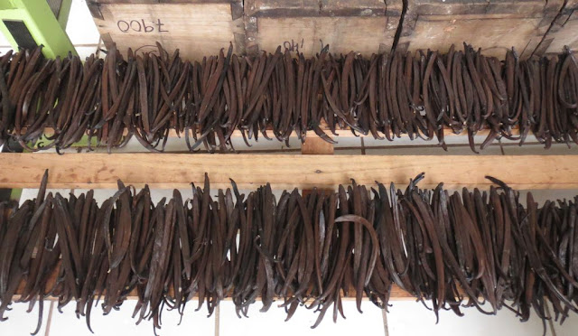
That brings us to the question of viability. Why Uranus? It is a fascinating, unconventional planet with a lot to explore, but scientific endeavours do not sustain a permanent population.
If we take settling planets to be an endeavour driven at least partially by comparative economic advantage, then the atmosphere of Uranus holds no advantage and therefore is of no interest. It is a dry, empty and dark desert not worth living in.
Its unique characteristics cannot be enjoyed without supremely advanced pressure- and temperature-resistant technology
Just outside the planet is another matter. Low Uranian Orbit could be a position of interest.
A space habitat orbiting at an altitude of 26,000km from the center of the ice giant (about 450km from the top of the atmosphere) would have a velocity of 14.9km/s. This means that atmospheric gas scooping is feasible with the propulsion systems we have available already.As described in Low Earth Orbit Atmospheric Scoops, the portion of gases collected by a scoop that have to be diverted for use as propellant depends on the ratio of exhaust velocity to orbital velocity. If the exhaust velocity is lower than the orbital velocity, more propellant must be consumed than is being captured. If they are equal, all gases entering the scoop must be expended as propellant. We want the highest practical exhaust velocity to consume the least gas as propellant and conserve as much of it as possible.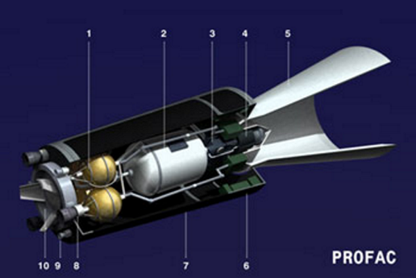
If we want to conserve at least 50% of the gases collected, we want double the orbital velocity as our exhaust velocity.
For Jupiter, this would mean upwards of 140km/s. For Saturn, it is still a huge 50km/s. Uranus is more reasonable with 30km/s required.
While all of these exhaust velocities are achievable, they come at a cost. The thrust delivered by an engine with 140km/s exhaust velocity requires 4.67x more energy than from an engine with 30km/s exhaust velocity. This means that for the same amount of fuel to provide power, you get 4.67x more gas out of Uranus than Jupiter. It is an important consideration when the fuel is likely to be uranium shipped from the Inner Solar System at great cost.
What use are gases scooped from the Uranian atmosphere?They would be condensed into a liquid, mostly hydrogen, and could be used to refuel spacecraft that aerocapture into the Uranian system, or refill propellant depots supplying space-only (do not land) transports between the Uranian moons. As we will see later, they will be needed for keeping critical infrastructure in orbit around the moons.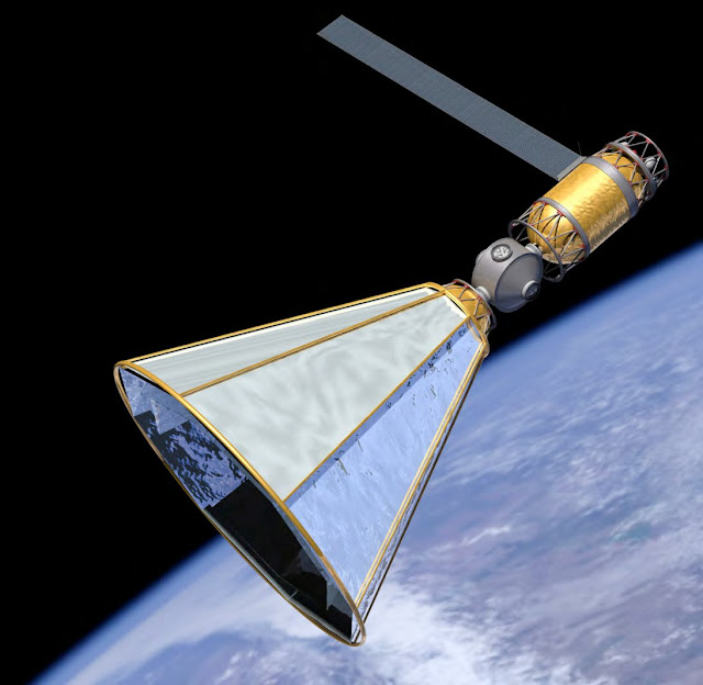
The moons
Unlike the other gas giants, the moons of Uranus are disappointing.The small moons, inner and outer, are assumed to be low density groupings of ices and dust. Frozen water, ammonia and CO2 are abundant in the Outer Solar System, so mining the small moons is not a good reason to go to Uranus.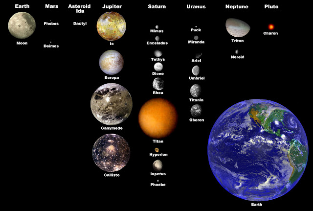
The large moons have rocky cores that are certain to contain useful metals and minerals. However, they are locked away under hundreds of kilometres of ice.
They do not have the vast oceans of the Saturnian moons, or the energetic environment of the Jovian moons.
Of some interest however is the moon Miranda.Miranda is the smallest major moon with a diameter of 480km. It is not very dense (1200kg/m^3), suggesting it is mostly water ice. Surface gravity is a tiny 0.079m/s^2, about 124 times less than on Earth.
What sets it apart from the other moons is that it is unlikely to be strongly differentiated into a core of rock and mantle of ice. Evidence from the Voyager 2 mission suggests that it suffered multiple giant impacts in the past. This would have brought up core material to the surface, to be buried again by ice.
The pressure at the center of Miranda should be about 20 to 25 MPa, which corresponds to 200 to 250 times sea-level atmospheric pressure on Earth. We have submarines that have reached the depths of the Marianas Trench, where the pressure is 1,000 times sea level pressure.
It is therefore possible, to dig through the entire length of the moon in search of rocks buried in the ice. They can be located from orbit by mapping their effect on the local gravity – as the rocks would be two to three times denser than the surrounding ice, they can be easily distinguished.
The effort of digging through kilometres of ice is not a trivial task, and it is unlikely to be favourable from an energetic and cost standpoint when compared to directly accessing similar rocks in the form of asteroids or rocky bodies.Ariel is the second smallest major moon around Uranus. It is 1,156km wide, big enough to be completely differentiated into an ice mantle 208km thick and a voluminous rocky core. It is densest of Uranus’s moons at 1592kg/m^3, so it has the greatest proportion of rocks and possibly heavy metals.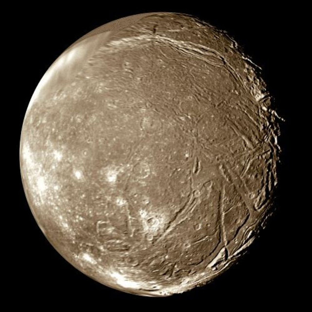
The low gravity means that reaching the interface between ice and rock requires handling pressures of only 56 MPa. It is speculated that a subsurface ocean might still exist around the core. It would certainly make moving around and digging out core material much easier… perhaps to the point where it would be cheaper to extract minerals and metals from Ariel than from asteroids.
There is an important comparison to be made between mining resources from the depths of these moons instead of extracting them from asteroids. If it is cheaper to get what you need from asteroids, then no-one will attempt to gather them from the moons, and if this turns out to be the case, then there is no longer a strong argument to settle the moons at all!
Because we can’t reasonably make comparisons based on price decades or centuries into the future, we must find something else. We will look at the energy cost of extracting resources.
Asteroid resources are easy to extract. They do have to be moved however. Altering the trajectory of a portion of, or all of, an asteroid has an energy cost proportional to the deltaV imparted to it.
Asteroid groups like the Jovian Trojans, Uranus Trojans or the outer solar system Centaurs, are the closest to Uranus and require the least energy to obtain. They are nearly entirely composed of frozen volatiles like ammonia and water ice. Some, such as 10199 Chariklo or 2011 QF99, are huge at 223 and 60km diameter respectively.
Asteroid group near Uranus. It takes about 5km/s of deltaV to move anything near the orbit of Jupiter (5.2AU) to near the orbit of Uranus (19.2AU on average). It then takes another 5.5km/s to spiral down from the end of Uranus’s sphere of influence to a major moon like Ariel, assuming a low thrust propulsion system is in use. Therefore, gathering ‘nearby’ asteroid resources requires between 10.5 and 5.5km/s of deltaV, which is an energy cost of 55.1 MJ/kg to 15.1 MJ.kg.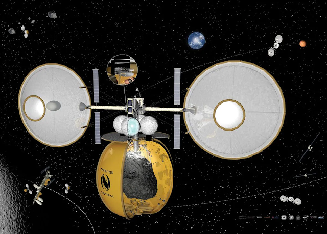
The issue with this analysis is that the composition of the asteroids that are ‘nearby’ is very similar to that of the Uranian moons. There is no point in collecting ice at several MJ/kg when you can just scoop it up from a moon like Juliet or Mab.
That leaves the other type of asteroid. The drier bodies, rich in carbon, silicates, minerals and metals. These are mostly found in the asteroid belt orbiting between Mars and Jupiter, at 1.5 to 3.5 AU from the Sun.The deltaV required to move this material up to our ice giant’s orbit is now 12.8 km/s (for 1.5 AU) to 7.2 km/s (for 3.5 AU). Add in the cost of spiralling in, and deltaV requirements become 18.3km/s to 12.7km/s. This translates into an energy cost of 167.4 MJ/kg to 80.6 MJ/kg.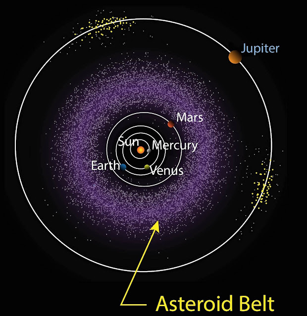
Every kilogram of material gathered from asteroids must expend that amount of energy. It is a minimum amount, so larger and larger scale transportation of resources only helps approach this cost. One intangible cost here is the years of travel required to move the resources. DeltaV calculations done so far are based on Hohmann transfers, which usually require the least energy to perform, but take the longest. A transfer from Mars’s orbit to Uranus’s orbit takes 16 years…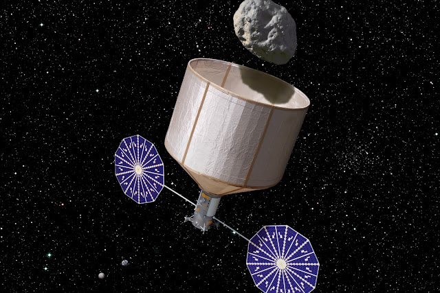
Keck asteroid capture mission.
How does this compare to digging into the Uranian moons?
A brute force assumption is to calculate the energy cost of melting through a column of ice from the surface to the interior of a large moon. This creates a column of water that can be kept liquid through continuous heating. We have done similar things in Antarctica.
In other words, this is a big up-front energy investment (melting the column) and a continuous cost (keeping the water liquid). Let’s try to calculate these costs.We will assume a large 10m wide column is dug initially, followed by a huge 200m wide expansion. The reasoning behind this is that settlements are likely to be permanent, or at least last for decades. A large column costs more to create but it reduces the surface area to volume ratio, which means less continuous heating is required. 10m is about the size of a mine shaft for a deep underground mine.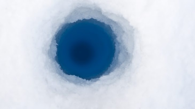
Ariel’s and Miranda’s surface temperatures are 60 Kelvin. If Ariel has a liquid or near-liquid layer around the core, then this temperature rises to about 270 Kelvin. Miranda however is too small to retain heat and therefore its interior temperature is probably around 180K (the minimum temperature for the cryovolcanic activity observed on the moon is 176K according to this).
Water ice has a heat capacity of 2.2 kJ/kg/K. It therefore takes 240kJ to warm 1kg of ice throughout Ariel to its melting temperature, and 264 kJ in Miranda.Another 333 kJ/kg is needed to transition from solid to liquid. We will also add a 10K margin to prevent random freezing of the water, so that adds 42 kJ/kg.The total comes out to 615 kJ/kg for Ariel and 639 kJ/kg for Miranda.
The density of ice is between 910 kg/m^3 and 940 kg/m^3 at these temperatures. We’ll use an average of 930 kg/m^3.
The column on Ariel would have to be 208km deep. On Miranda, it is hard to estimate. It is a broken moon where parts of its core could be close to the surface. It has canyons 20km deep, which serve as a good starting point. We can take a conservative estimate and say that two thirds of its radius is sufficient, so 160km. From these figures, we obtain the following data table:
Ariel10m column1.63*10^7 m^31.52*10^10 kg9.3*10^15 Joules200m column6.54*10^9 m^36.08*10^12 kg3.74*10^18 JoulesMiranda10m column1.25*10^7 m^31.17*10^10 kg7.47*10^15 Joules200m column5.03*10^9 m^34.67*10^12 kg2.98*10^18 Joules
Let’s move onto the continuous heating.
The temperature difference between the water and the surrounding ice dictates how much heat is lost through thermal conduction. This can be reduced significantly by thermal insulation. The insulation can hang off whatever structural support is put into place to prevent the column from collapsing.A 10cm thick layer of mineral wool that can be made using the rock waste from other mining operations is a good option. Here is the heating requirement data: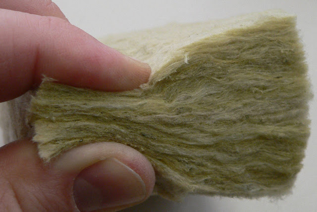
Ariel47 W/m^2 lost on average307.2 MW for 10m6143 MW for 200m
Miranda65 W/m^2 lost on average326.7 MW for 10m6535 MW for 200m
This is a continuous energy expenditure.
You might be wondering about the energy cost of raising material from the bottom of the column to the top. It will not be calculated because there is a ‘free’ solution: buoyancy. A bag of material can be floated to the top on bags filled with gas. It is one of the advantages of a water-filled column. The other advantage is that the weight of the water pushes back against the external pressure and reduces the structural support requirements.Now these are all big numbers! How do they compare to asteroid mining?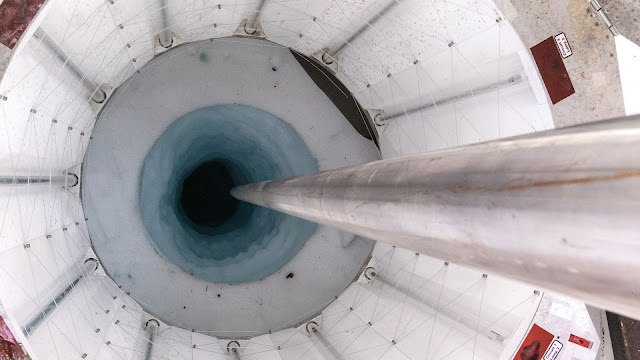 We know now that setting up a mine on one of the Uranian moons costs a huge deal of energy, and then many megawatts of energy are needed to prevent it from freezing closed. An asteroid mine is assumed to cost nothing to set up from the perspective of Uranian settlers, but asks for many megajoules for each kilogram delivered and years of waiting for the first delivery or for any updates to the required raw materials to be executed.The initial energy cost is not a deal-breaker on its own. The 10m wide column on Miranda can be created through the work of a 1 GW nuclear reactor and a steam drill for 12 weeks. A giant 200m wide hole can be pierced through Ariel’s icy crust in one year if 118 GW of heat is used.
A useful calculation to perform is the breakeven point at which a hole through Ariel or Miranda becomes the better option over mining asteroids at 80 MJ/kg. It will depend on the quantity of material being extracted and moved up the column.
Here are the results:
Ariel10m columnBreakeven in 1 year: 237,348 tonsBreakeven in 5 years: 144,348 tons per yearBreakeven in 10 years: 132,723 tons per year200m columnBreakeven in 1 year: 49,171,570 tonsBreakeven in 5 years: 11,771,570 tons per yearBreakeven in 10 years: 7,096,570 tons per yearMiranda10m columnBreakeven in 1 year: 222,160 tonsBreakeven in 5 years: 147,460 tons per yearBreakeven in 10 years: 138,122 tons per year200m columnBreakeven in 1 year: 39,826,097 tonsBreakeven in 5 years: 10,026,097 tons per yearThese production rates are not excessive. The break-even point for a 10m hole is equivalent to a small mining operation today (~400 tons per day). The large column is representative of the mining needs of a small country. Remember, these tons represent every resource from calcium to titanium. Going by usual terrestrial crust composition, 7 million tons of raw rock extracted only represents 133 tons of gallium or 19 tons of uranium. If the need for these elements is greater than these quantities, then deep Uranus mining is cheaper than moving asteroids.Note than we have used the less energetically expensive 80 MJ/kg figure and the same 10cm thick insulation for the small and large diameter columns. In reality, there will be a mix of asteroid sources of up to 160 MJ/kg, and the insulation can be gradually thickened. The 200m width of the Miranda mine would have room for 1m thick insulation, cutting the heating requirements to 6.5W/m^2 and the breakeven in 10 years figure to just under 4 million tons per year.
So what does mean for Uranian settlers?
A colony is likely to be based on Miranda if mineral deposits are found near the surface, or on Ariel otherwise.It will dig chambers at a sufficient distance under the ice to protect it from radiation. Using hot water as a digging tool is effective. The initial source of energy would have to be a nuclear reactor.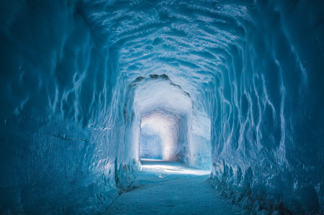
The colony would be reliant on interplanetary shipments or resources, people and fuel to set itself up. This could represent years of money being spent with nothing being obtained in return. Unlike Jupiter or Saturn, there would be no ‘novelty’ factor and reduced scientific benefit.
Primary objective would be self-sustainability. Reducing dependence on external suppliers is necessary because the cost of transport is greatly increased by the travel times and distances. We think Jupiter is far away from Earth, orbiting as it does at 5.2 AU. Uranus sits four times further. One factor that would help this colony come into being is the existence of colonies on Saturn. Resources from Saturn would be massively cheaper than shipments from the inner solar system.
However, Uranian colonists would still want their own supply as it is necessarily cheaper than any interplanetary shipment in the long term.
The path to self-sustainability involves digging these columns, finding a source of power and securing a trade advantage to start becoming profitable.
How can colonies on Uranus power themselves and become profitable? The answer is in the next section.
Uranus Lunar Inter Orbital Kinetic Energy Exchange
Uranus has a number of small moons that orbit at very different velocities. They can serve as the only large-scale source of energy for settlers on this planet.The concept of a Kinetic Energy Exchange involves accelerating and catching masses between different orbits. More energy is gained than consumed, as it is extracted from the momentum of the moons used as starting and ending points of the exchange. For a full description, read this previous exposition on the concept: Inter Orbital Kinetic Energy Exchanges.
To generate power, we will have launchers accelerate masses into trajectories that intercept receiver stations orbiting moons where colonies are located. The launchers can be self-powered by a nuclear reactors, or by laser beams from the colonies.
We will keep calculations simple by only looking at the two more promising colonies (Ariel and Miranda) as destinations for the masses, and only at Hohmann trajectories.The first table displays Hohmann trajectories.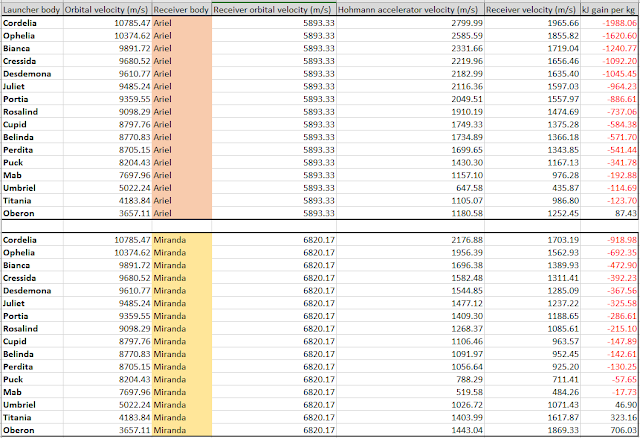 Launcher body is the moon where the launcher is positioned. It is assumed to be a coilgun with good efficiency, powered by a nuclear reactor. It shoots projectiles using modest accelerations, so that they can be fitted by a guidance and propulsion system that helps them intercept a receiver accurately.
Orbital velocity is the velocity of the moon where the launcher is positioned, noted in meters per second. The moons further out orbit at slower speeds than the small moons close to Uranus.
Receiver body is the moon where the receiver is positioned. We are interested in Ariel and Miranda. The receiver works like a launcher, but in reverse. Magnetic fields are used to slow down the projectiles, and in doing so, their kinetic energy is converted into electricity.
Receiver orbital velocity is the orbital velocity of the moons Ariel or Miranda, also in meters per second.
Hohmann accelerator velocity is the velocity to which the projectiles have to be accelerated so that they perform a Hohmann transfer that intercepts Ariel or Miranda. In meters per second.
Receiver velocity is the velocity at which the projectiles meet the receiver. In meters per second.
kJ gain per kg is the final result. It is the energy difference between the expenditure of the accelerator and the conversion into electricity at the receiver, measured for 1 kilogram. If it is negative, then more energy was spent accelerating the projectile than was gained at the end. If it is positive, then energy is being taken from the momentum of the moons and added to the colony.
All launchers are assumed to be fixed to their bodies. The effect of gravity on the required launcher velocity is ignored for the small moons, but for the large moons, it means that the projectile is slowed down until it escapes the moon.
This is why the escape velocity of Umbriel, Titania and Oberon is added to the required accelerator velocity.
From the results, we see that only projectiles launched from Oberon allow for a gain in energy at Ariel, but a colony on Miranda can make energy out of any accelerator on Umbriel, Titania or Oberon. This makes sense, as shooting out and ‘up’ from the inner Uranian moons costs energy but shooting inwards and ‘down’ in the direction of the gas giant’s pull gains energy.
The second table is for Hohmann trajectories with orbital velocities around the moons included when relevant.This time, we have the launchers and receivers orbiting their moons. For launchers around the big moons, we have a boost which accounts for the 71% of the escape velocity. Oberon for example has an escape velocity of 717m/s and then a Hohmann transfer velocity to Miranda of 1,252m/s, creating a requirement for 1,443m/s at the accelerator (it is the root of the sum of their squares). If we have a launcher orbiting at 507m/s, then this requirement is reduced to 935m/s.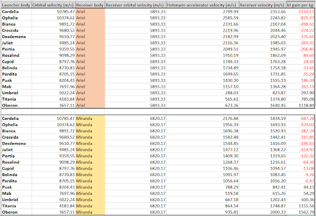
The same goes for the receivers. Objects in low orbit around Ariel travel at 388m/s, and those around Miranda at 131m/s. This is added to the projectile velocity at intercept.
kJ gains per kg is now much more interesting. As before, the optimal launcher locations are the large moons closest to Ariel and Miranda, with Oberon coming out on top. Because of the need for the moons to be in the correct positions, this will likely take the form of a reactor charging a large flywheel or capacitor in between launches. All the energy is discharged at the optimal Hohmann launch window. Each 1 ton of projectiles exchanged costs 437 MJ at Oberon but delivers 2,000 MJ at Miranda, for example.
The downside to this configuration is that the energy from the receiving station must be delivered to a colony on the ground. The best way to cross the short distance between the low orbit altitude and the ground is to use a microwave beam and a rectenna to convert the electromagnetic radiation back into electricity at very high efficiency.
This third table is more extreme. It makes maximal use of the possibility to beam energy between moons using lasers.Instead of transferring energy only in one direction, from a moon in a higher orbit to Ariel or Miranda in lower orbits, the launchers can send projectiles down to the innermost moons and beam back the energy to the colonies.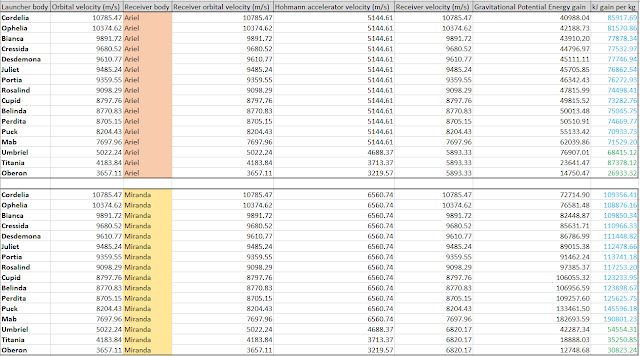
The advantage is that much greater orbital energies become accessible.
Even better, we can ditch Hohmann trajectories for higher cost, higher reward straight-line trajectories where we first cancel out the orbital velocity, let a projectile drop straight down to Uranus and then intersect a moon at a lower orbit. The relative velocity becomes the sum of that lower moon’s velocity and the velocity of the projectile from falling to Uranus. That is why we now have an extra ‘Gravitational Potential Energy gain’ column in kJ/kg.
For the small inner moons Mab to Cordelia, we assume that a launcher on Ariel or Miranda is used to cancel out their orbital velocities and let a projectile drop. For the larger moons, we assume a launcher is dropping projectiles on Ariel or Miranda.
So, for example, a launcher in low orbit around Ariel would require 5,505m/s to get a projectile to start falling towards Uranus, which is reduced to 5,144m/s if we start in low orbit. If it intersects the orbit of Cordelia, it could meet a receiver at a relative velocity of 10,785m/s. This costs 13.2 GJ per ton but delivers 99.1 GJ.
The disadvantages of this method is that the launchers and receivers need to be much larger to handle the required higher velocities. The process of converting from electricity to laser light and back, and having the beam cross tens of thousands of kilometres, will involve certain losses and a lot of infrastructure, such as relay mirrors orbiting between the moons.
On the other hand, cryogenically cooled lasers are very efficient and positioning mirrors is a small investment compared to the other projects required to start up a colony on Ariel or Miranda. Furthermore, the energy being beamed from the receiver back to the colony can also be used to recharge the launcher, which allows for the limitations of an on-board nuclear reactor to be dispensed with and essentially limitless energy to be unlocked.
Also, energy generation is no longer constrained by Hohmann transfer windows that could be separated by weeks or months, and we could imagine expansions where energy gain is maximized. For example, a captured asteroid could sit at 10 million km from Uranus and an accelerator would only need 760m/s to cancel its orbital velocity. The receiver could be positioned in Low Uranus Orbit and zip around at 15km/s and use atmospheric gas scooping to maintain its altitude. Projectiles exchanged between these platforms could gain up to 334MJ/kg. This is three times better than the best value in the third table.We can confidently say that InterOrbital Kinetic Energy Exchanges can fulfil the energy needs of settlements around Uranus. A lot more effort, time and money will have to spent on setting up these exchanges compared to the simple solar panels or wind turbines that are available to colonies on other planets, but once they are up and running, they will be a competitive option.
Uranus Interplanetary InterOrbital Kinetic Energy ExchangeThe network of launchers and receivers around the moons of Uranus can be expanded to shoot projectiles across interplanetary distances. It becomes possible for a colony on Uranus to ‘export’ energy to the other planets or more importantly, space habitats in the Outer Solar System.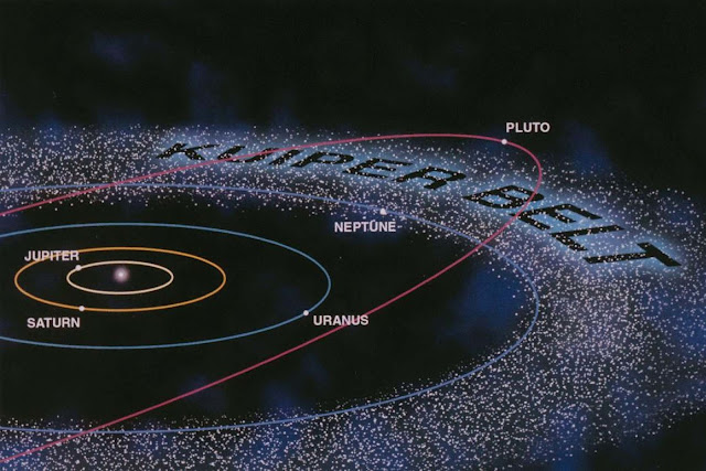
As we will show, planets that are closer to the Sun than Uranus can receive a lot of energy thanks to the multiplication effect of InterOrbital Kinetic Energy Exchanges, but they have plenty of alternative energy sources. Habitats in the Outer Solar System do not have the same options. Solar power is very weak, nuclear power must be imported at great cost, and the asteroid or comets they work with are cold objects with no intrinsic energy potential. Beamed energy struggles to cross the millions of kilometres that separates them from their closest neighbours, but projectiles can travel indefinitely along certain trajectories.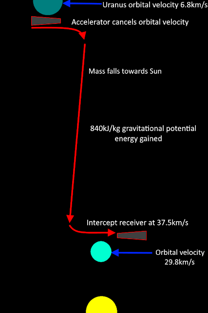
Example of a kinetic energy exchange between Uranus and Earth.
As before, here is a data table on the kinetic energy exchanges that are possible using Hohmann transfers from an accelerator in Low Uranus Orbit:We have included hypothetical receiver stations at 3, 10, 20 and 30 AU orbits to represent any colonies not orbiting a planet or moon. In all cases, it costs more energy to deliver projectile to them than it does to generate that same energy in-situ. However, as stated before and especially for stations in the 20 and 30 AU orbits, there may be no alternative energy source.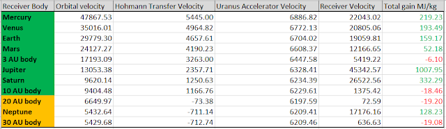
For receiver stations orbiting planets, we find that the additional boost from low orbit velocity is very helpful. For example, a projectile on a Hohmann trajectory from Uranus to Jupiter would intercept the latter at 3,320m/s. A receiver station in Low Jupiter Orbit is orbiting at about 42,021m/s and would therefore come up to meet the projectile at a combined velocity of 45,342m/s, allowing for a whopping 1 GJ/kg to be gained with each kinetic energy exchange.
What could be understood from this table is that using simple Hohmann transfers, Uranus could deliver considerable amounts of energy to the entire Solar System.
We can do better. Here is a table where the accelerator is positioned not in a Low Uranus Orbit, but near the edge of the Uranian gravity field:Because the projectiles do not have to fight Uranus’s gravity on the way out to interplanetary space, the accelerator velocity now equals the Hohmann transfer velocity.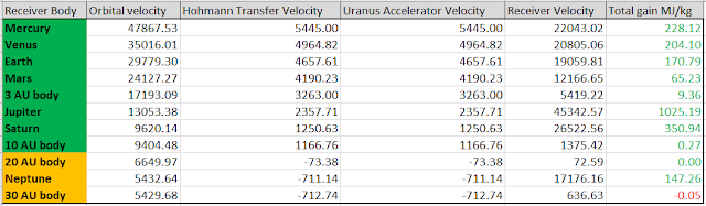
The difference is small when shooting projectiles at the inner planets or those with very high low orbit velocity like Jupiter, but it becomes significant for targets like Neptune. It also becomes a net positive gain to send energy to habitats orbiting at 3 or 10 AU, and only a minor loss for habitats at 20 or 30 AU.
Finally, the extreme case. Non-Hohmann trajectories where we cancel out Uranus’s orbital velocity around the Sun, and with the launcher positioned at the edge of the planet’s gravity field:The list is shorter because projectiles accelerated in this manner can only fall towards the Sun, and so cannot reach higher orbits. Note that the transfer velocity is exactly Uranus’s velocity around the Sun.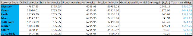
Receiver velocity is the combined orbital velocity of the planet and the low orbit velocity of the receiver station around it. Earth, for example, would add up its orbital velocity of 29,779m/s and its Low Earth Orbit velocity of 7,780m/s, for a total of 37,559m/s and an energy gain of 1.5GJ/kg.
The gains are very high for the inner planets (and Jupiter) and very interesting for stations at 3 and 10 AU from the Sun. They do not benefit from any low orbit velocity because they are not orbiting any other body than the Sun, so maximizing the receiver velocity is very important.
The challenge with this method is that you need to start off with a large mass far from Uranus, or find a way to deliver projectiles from a colony closer to Uranus as well as propellant to keep the accelerator in its orbit.
All calculations can be found here.
What can we take from all this?
The viability of a colony on Uranus might depend on it being able to shoot out projectiles all over the rest of the Solar System. It would be a big energy provider that does not depend on any fuel source and can infinitely expanded.
There should not be any concerns about displacing the moons of Uranus because of this. Slowing down Ariel by 5m/s would yield enough energy to keep our current 20 TeraWatt civilization running for 30 years.
Trajectories and methods described so far are rather simplified and there is much more potential to them. It is possible to imagine that the projectiles use solar pressure or electric propulsion to speed themselves up. Or, they can use gravity assists to reduce the accelerator velocity and still arrive faster at their destination.
The projectiles’ momentum can also be used. A receiver station on an asteroid will absorb the recoil and transfer it to the body it is attached to. This can slow down or accelerate an asteroid, essentially becoming an asteroid moving tool with no reactor or engine of its own.
The projectiles can also contain something of value. They can be shaped into robust containers for something like Helium-3 or platinum.
The value of a colony on Uranus increases as it finds more and more creative way to exploit its position far above the Solar System.
The colony
Let’s briefly describe what a colony around Uranus would look like.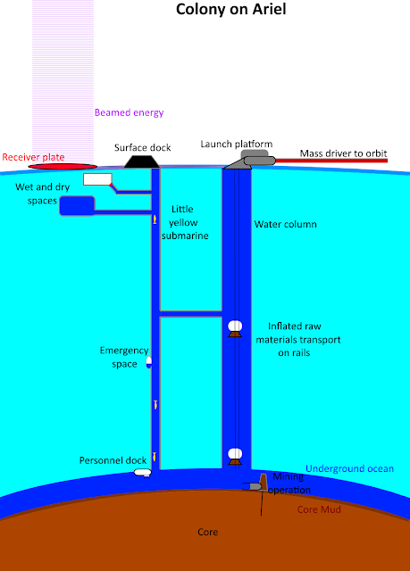
Do zoom in!
Our location pick is Ariel.
It sits as a network of flooded tunnels inside the ice near the moon’s surface. Two major structures stand out: columns of water extending down to the salty ocean surrounding the core.
The ‘down’ column is smaller, as it exists mainly to send personnel and equipment to the core. The ‘up’ column must accommodate a flow of raw materials and inflated transports that propel them up to the surface, and is therefore much larger.Flooded tunnels allow for the same buoyant devices that transport raw materials and equipment to used from core to the surface without the need to traverse from wet to dry environments and all the complicated docking requirements that implies.
The actual living spaces are dry, insulated bubbles within the ice connected by the flooded tunnels. The bubbles are positioned above the tunnels and are equalized in pressure, so there is never any risk of the water spilling into the dry environment. Closed hatches seal off the tunnels to prevent excessive humidity, but they don’t have to be airtight or fight against pressure differences.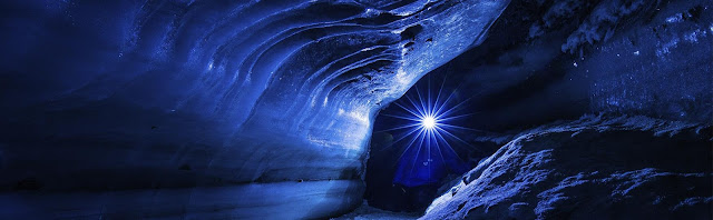
Ice caves!
Work spaces can be dry, wet or partially flooded according to the colony’s needs. For example, offloading raw materials would be done in a partially flooded space, which would act like a canal dock. Repairing a transport craft could be done in a work space that starts off wet so the craft can be floated inside, and then drains to become a dry space so that the craft rests on scaffolding accessible by workers.
Transport craft carrying raw materials would be slow. They would sink or rise along cables acting as guide rails. Arrestor hooks prevent it from crashing into other transports beneath it in case its inflated balloon pops. Transport craft for personnel are likely to have propellers to speed up the journey and emergency life support in case it gets stuck. Travelling up and down a 208km deep column at 20km/h (10.8 knots) takes over 10 hours each way.
Because of the length of travel, pit stops in the form of solid-walled, surface-pressure habitats that transport craft can dock with would be positioned at regular intervals. These are also good places to form passages to adjacent columns as the network expands. In the further future, they could develop into hubs for workers that want to shorten their commute to the core and live near their place work, and eventually into fully-fledged subterranean ice colonies.
The core and its surrounding ocean is the reason what all this effort is for.
We believe that it is a salty ocean mixed with ammonia and perhaps ethanol. That makes it a good source of hydrocarbons, nitrogen and minerals like sodium and potassium.The core’s top layers are likely to be cold mud. It can be ‘washed’ in-situ to separate out insoluble components like metals, or it can be delivered whole to the surface to be processed.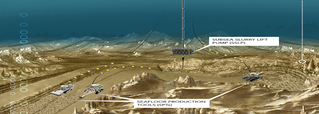
While we do not know what ‘core mud’ will contain, we can guess that it experienced heated from radioactive decay and is generally similar to that of the rocky planets, since they formed of the same primordial material, but with a much reduced metal center, perhaps not even fully concentrated into one sphere but scattered as enriched deposits around the central volume. Either way, we are likely to find all the ingredients necessary to build a colony and keep a large population alive. There would be no critical shortage of one element or another.Digging further into the core would reveal depths better enriched in the more interesting elements like nickel, iron, uranium and platinum.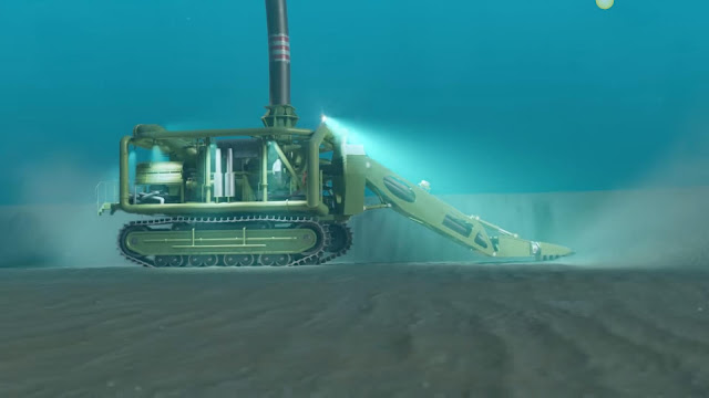
Most of the rest is worthless though. ‘Wastes’ like silicates would make good fillers for the projectiles used in interorbital kinetic energy exchanges.
Evolution
The colony will start big.
This is a necessity. Only in a Solar System where Jupiter and Saturn are colonized and there is active interplanetary trade does Uranus seem a worthwhile expansion. And, because of the implied scale of the rest humanity’s activities off Earth, it will have to quickly grow to a size that meets needs at planetary scales.
The initial investment of digging down to a moon’s core through kilometres of ice and installing giant accelerators and receiver stations that can handle large projectiles at up to a dozen kilometres per second, all while collecting the energy they gather into beams that cross thousands of kilometres, will not make it possible for small, private ventures to try their hand at colonizing Uranus.
It will be less family businesses and the Wild West, more like the Three Gorges Dam and the multi-billion corporate ventures of today.
An Uranian colony would also have to arrive after its potential customers are in place. These include a colony on Saturn and free-floating space habitats in the Outer Solar System. In other words, settling Uranus would have to wait until humanity has expanded to its second gas giant and the asteroid mining business has grown and moved past just searching for metals, and is now trading and delivering volatiles from the comets in far orbits.And, the advantages that Uranus has over Jupiter and Saturn are relatively slim. Despite all the opportunities described here, they can be done in a lesser capacity by those other planets. A non-Hohmann transfer from the edge of Saturn to Earth would cost 47MJ/kg and deliver 1.45GJ/kg. This is less impressive than Uranus’s 23MJ/kg for 1.52GJ/kg, but the potential for a large multiplier on energy gain is still there.
We would have to wait until that slim advantage is worth more than the huge initial investment mentioned previously. That could be centuries in the future. The obvious danger that comes with describing events that takes place centuries in the future is that new technologies, new social needs or radical changes could have occurred that are impossible to predict and could completely invalidate current extrapolation.For example, a terraforming effort on Mars could call for vast amounts of water and other volatiles. These would originate from comets far away from the Sun, as they are the easiest to displace from their orbits and smash into Mars… which would make an Uranian colony ideally situated to service them with energy, minerals and metals. Or, fusion propulsion is perfected and travel around the Solar System becomes rapid and low-cost. There would be no need to compare MJ/kg values for obtaining resources, nor would interorbital kinetic energy exchanges remain worthwhile in the face of deuterium and helium-3 reactors… and thus the advantages of Uranus disappear.
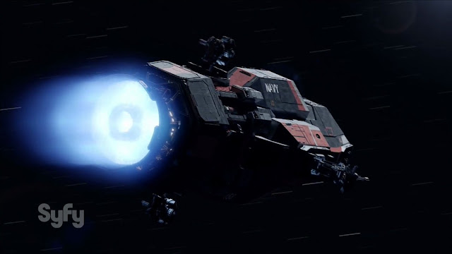
Still, with our current assumptions, we can expect the colony to grow as it finds more uses for its projectiles and new customers appear to make use of them. Greater populations will settle the Uranian moons, which creates an internal market.
Eventually, the ability for the projectiles to move asteroids can be exploited to bring rocky or metallic body to Uranus so that they become the primary source of raw materials at a lower incremental cost than digging new tunnels. This can only happen after the kinetic energy exchange network is in place, so we might see webs of columns and chambers within the ice abandoned after a few decades… that is certainly a unique and interesting setting for a science fiction story or game. -
This is amazing!
Have you tried flying this in FAR?
-
I am really impressed by the level of effort you're putting into this, with mission badges, edited photos and full descriptions. Love it all!
-
7 hours ago, magnemoe said:
Would not an multi staged craft work better? take an starship cargo craft. Put an probe with an hypergolic braking stage. Add an LOX / metane 3rd stage who is empty on launch, balloon tanks and one raptor. This stage along with starship is fueled in orbit. fully fueled this will be far heavier than an standard payload say 500 ton. Use starship for the first part of burn, something like GTO.
Release 3rd stage who continues while starship return to earth.
If you can keep the LOX and methane cool you could use this to brake and drop the 4th stage even if an 4th stage would be nice on an light high speed probe.I found that the deltaVs required for braking just could not be handled by chemical propulsion once you accelerate the trajectories.
For example, that trip to Mercury required over 14km/s braking burn. A hypergolic stage of 320s Isp would need a mass ratio of 86.5! The only real option is solar-electric.
And nuclear-electric is the only option for performing one of the very high deltaV braking burns at the Outer Planets.
-
This is from the latest ToughSF blog post: http://toughsf.blogspot.com/2019/05/starship-lite-from-rapid-interplanetary.html
Starship Lite: from rapid Interplanetary to Interstellar
Elon Musk stated that a stripped-down SpaceX Starship could become an interplanetary boost vehicle able to push probes towards the farthest objects in our Solar System.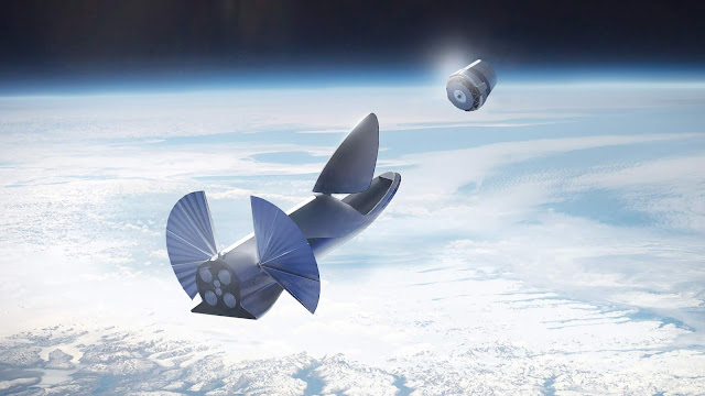 What other missions could the Starship ‘Lite’ do, and how quickly?Near SSTO
 Rockets performance scales favourably with size. A larger rocket dedicates less mass to propellant tanks, engines and other equipment relative to the quantity of propellant it can hold. In technical terms, bigger rockets have better mass ratios.The SpaceX Starship, planned to stand 55m tall, 9m wide and at 1350 tons on the launchpad, increasing to 118m and 4,400 tons once mounted on top of its giant booster stage, makes the most of its size.
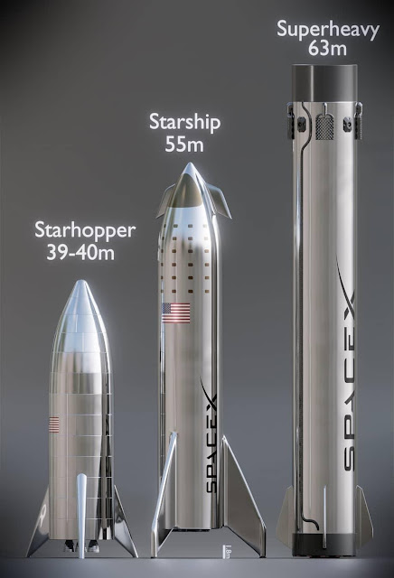
Art by Charlie Burgess. Despite being made of steel, the launcher manages a dry mass of 85 tons. The addition of landing legs, longer propellant tanks and large delta wings likely brings this closer to 90 tons. This gives it a mass ratio of (1350/90): 15. The current versions of the Raptor engines it uses have a sea-level Isp of 330s and a vacuum Isp of 360s. The average Isp over the course of a launch is about 350s.Tsiolkovsky’ rocket equation gives us the deltaV we can expect from the Starship:- DeltaV = ln(Mass ratio) * Isp * 9.81
The mass ratio is the dimensionless ratio of full to empty weight.Isp is in seconds, and multiplying it by 9.81 gives the exhaust velocity in m/s.We find that it can produce 9.3km/s of deltaV. This is enough to reach Low Earth Orbit, and validates claims that it can act as a single-stage-to-orbit vehicle.
Art by Charlie Burgess. However, these figures are for a Starship with no payload onboard except the vehicle itself, and no reserve propellant to perform a powered landing. Placing 100+ tons in LEO requires the help of the ‘Superheavy’ booster.Starship LiteElon Musk presented two versions of the Starship back in 2017: a crewed version and an uncrewed tanker or cargo-carrier version.The 85-90 ton figures are for the crewed version. It has to have a large habitable volume, life support systems and other contributors to a larger dry mass.The uncrewed version can dispense with all that. Its dry mass is reported to be 60-75 tons. The mass ratio increases to 18-22, as good as that of the Falcon 9 booster stage.This tweet from Elon Musk introduces what we’ll be calling the Starship Lite – a stripped-down version with no features meant for re-entry, recovery or holding a payload. It would be a naked steel tank with an engine at the bottom and used solely in space.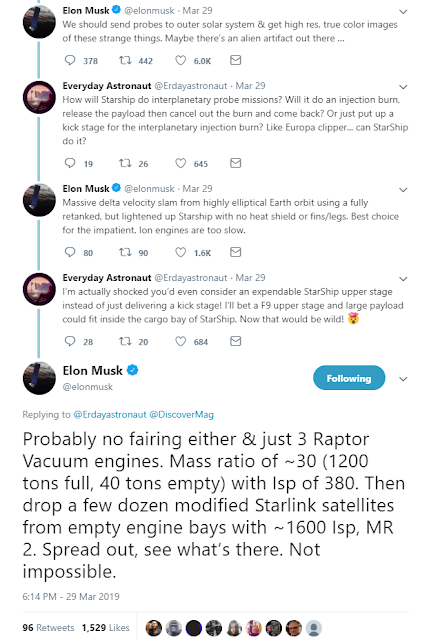 Starship Lite has a mass ratio of 30, from a wet mass of 1200 tons and a dry mass of 40 tons. It is unknown why the wet mass is lower than previously stated. The engines can be optimized for the vacuum environment – the addition of huge nozzles increases their Isp to 380s.Going through the deltaV equation again, we find a value of 12.7km/s.
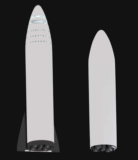
It will likely resemble the vehicle on the right. Art by 'teamonster'. The vehicle could start out sitting in Low Earth Orbit, fuelled and ready to go. It could be a regular Starship that was converted in space instead of returned to Earth. Filling it up would take about 12 tanker launches. Alternatively, it could be boosted into an extremely elliptical orbit, reaching out to beyond the Moon in apoapsis (400,000km) and just above the atmosphere in periapsis (200km). Tankers would struggle to match its orbit and deliver more fuel, increasing the number of launches required to fill it up to 70 (!).For the following sections, we’ll attach various payloads to the Starship Lite and work out which missions can be carried out and how quickly they can get to their destination.Ultima Thule and beyond
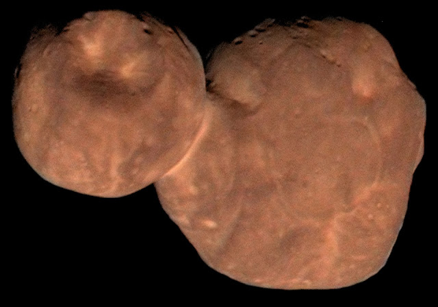 In that same tweet, Elon Musk talks about Starlink satellites converted into probes. They would have a solar-electric propulsion system with an Isp of 1600s, so with the mass ratio of 2, they’d have a deltaV of 10.9km/s.
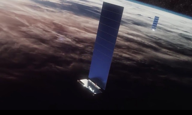 Between the elliptical orbit giving some starting velocity, a fully fuelled Starship Lite and the probes with their efficient engines, we can look forwards to some pretty extreme missions.Adding up the deltaV amounts, we can already tell that the probes can be put into trajectories that escape the Solar System. This is what probes Voyager I and II accomplished.Let’s look for the time required to reach the original goal: 2014 MU69 ‘Ultima Thule’.The asteroid orbits at a distance of 44.5 AU from the Sun on average. Because we don’t have a launch date, and we can assume that the launch will be optimally timed and won’t need an inclination adjustment, we can do some simple calculations.First of all, the Starship Lite is loaded with a couple of modified Starlink satellites. Let’s suppose 4 of them fit within a 1 ton payload. Mass ratio is reduced to 29.3To escape Earth, the loaded vehicle burns all of its propellant at periapsis. It is already travelling at 10.9km/s, to which it adds 12.6km/s of deltaV. This gives it an initial velocity relative to Earth of 23.5km/s.The Oberth effect is significant. Even after gravity slows down the Starship Lite, we expect it to shoot away into interplanetary space at a whopping 20.9km/s.Earth orbits at 1 AU from the Sun at 29.7km/s. The escape velocity from the Sun at Earth’s orbit is 42km/s. Our Starship Lite leaves Earth and enters interplanetary space 50.7km/s. Another way of putting it is that the Starship is going faster than the Sun’s escape velocity… so it will continue travelling beyond the Solar System and go interstellar. After millions of years, it will meet another star system. A true star ship.Kerbal Space Program, modified to represent the real Solar System, can give decent approximations of the trajectories possible. If the screenshots taken look too small to read on your screen, right click and open them to full size in a new tab. We position a target in Ultima Thule’s rough orbit and send off a model of the Starship Lite to meet it.
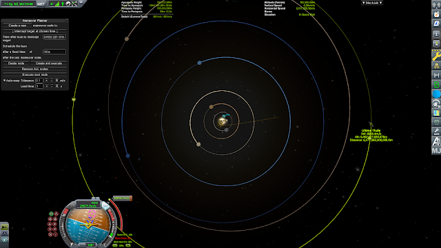 We find that Ultima Thule can be intercepted after about 6 years and 10 months. Our Starship Lite would pass the asteroid by at a blistering 28.6km/s!
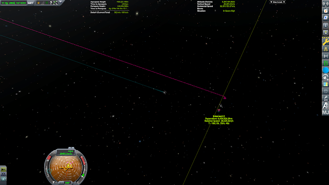 Let’s add the deltaV from the probes’ electric engines on top. They can raise the velocity at which they escape Earth by another 10.9km/s, allowing for a total of 31.8km/s relative to the Earth, or an incredible 61.6km/s relative to the Sun.The increased velocity shortens the travel time to 4 years and 7 months and the modified Starlinks cross the asteroid’s path going even faster. The biggest challenge would be resolving the asteroid in the probe’s cameras before it is out of sight again!To the planets, quicklyThere is plenty left to explore in the Solar System despite decades of probes and dozens of robotic missions. Scientists would love to be able to send a heavy probe loaded with instruments, RTGs, propellant and radiation shielding for long-duration missions to places such as Mercury or Uranus.
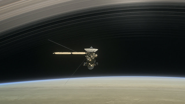 The Cassini-Hyugens mission put a lander on Titan and orbited Saturn for 13 years. It represented a 5.7 ton payload. Using the payload capacity of the Starship Lite, we can put together a bigger, heavier and more capable probe. Since we want the probe to spend a long time doing science instead of flying past like at Ultima Thule, we need to have a way to brake and insert the probe into an orbit around its destination. This means that the probe needs propulsion capability.Now, working out the optimal probe mass ratios, power densities, ion engine endurance and all the other factors that go into proper mission design would take weeks of work and accurate simulation tools. ToughSF does not have access to those resources… so we will cut short the work by fixing the probe mass at 25 tons.Depending on the mission parameters, those 25 tons could be nearly entirely dedicated to scientific equipment (24 tons dry mass, 1 ton propellant), entirely filled with propellant (1 ton dry mass, 24 tons propellant) and anything in between.
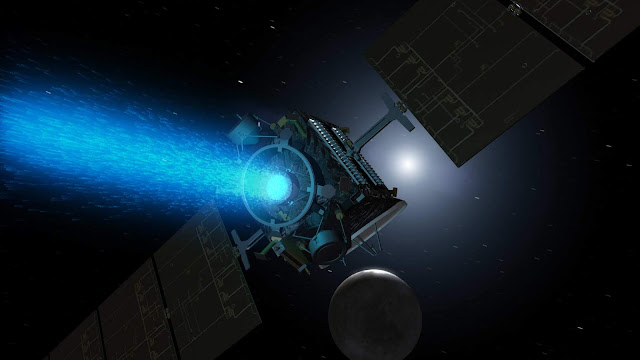 The exact propulsion type is left open. A hypergolic-fuel system with 320s Isp, where a lightweight 2 ton probe carries along 23 tons of propellants would have a deltaV capability of 7.9km/s would be ideal for a rapid gravity assist maneuver deep in Jupiter’s gravity well, where the radiation environment makes solar power tricky at the very least. A Starlink-like electric engine would work best when braking into orbit around Venus or Mercury, where abundant sunlight allows for decent acceleration. Going further, we could even expect a nuclear-electric power system and a HiPEP-derived 6000s Isp engine slowly accumulating velocity in the Outer Solar System; with a mass ratio of just 1.5, it would have a whopping 23.8km/s to perform a braking maneuver at Uranus or Neptune.Furthermore, we won’t be using the complicated and expensive elliptical orbit as a starting point. While it might be worth it for a once-in-a-lifetime opportunity to visit an interstellar asteroid leaving the Solar System, it would be too expensive of an option for the exploration of our planets. Instead, we will assume a straightforward and cheaper 1,000km starting altitude.We can go ahead and focus solely on the outbound trajectory from Low Earth Orbit. Where could Starship Lite position this 25 ton probe and how quickly could we get there?A 25 ton payload increases the Starship Lite’s dry mass to 65 tons. This decreases the mass ratio to 18.46, and its deltaV capability to 10.9km/s.From Hohmann trajectory data, we know that this is enough to reach every single body in the Solar System.
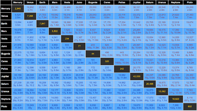 However, relying on these trajectories means sometimes waiting for many decades for the probe to reach its destination. Instead, we will look at higher energy trajectories. We rely on Kerbal Space Program again to obtain approximations.Let’s start with Mercury. It is a difficult planet to get to. The latest attempt, BepiColombo, has to perform multiple flybys of Earth, Venus and Mercury before it can enter Mercury’s orbit 7 years after lift-off. We won’t be so patient! We’ll make for a single transfer to Mercury.
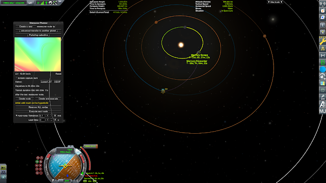 We find that 10.9km/s is enough for a quick 55 day trip to Mercury.Venus is closer. Earth’s sister planet was last visited by JAXA’s Akatsuki probe in 2010, where it failed to reach the desired orbit due to a malfunctioning engine. It had to wait 5 years before it could try again.
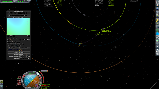 The ‘porkchop’ plots show us a way to get to Venus in a mere 30 days.Mars has had a permanent robot population since 1971. Insight, the newest inhabitant, took about 7 months to get there.
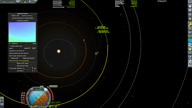 According to our approximation, we could cut that down to 40 days with the Starship Lite.Jupiter is far away. Juno had 4 years and 10 months of drifting through space to reach the gas giant.
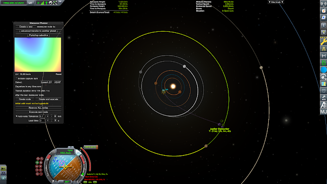 A more energetic trajectory can carry a 25 ton probe to Jupiter in just under a year.Saturn can be reached with a Hohmann trajectory lasting 73 months. Cassini-Hyugens took about this long to have a look at the Solar System’s most impressive rings.
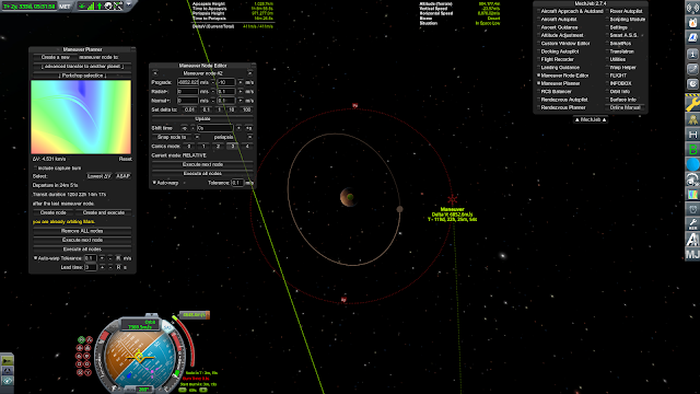
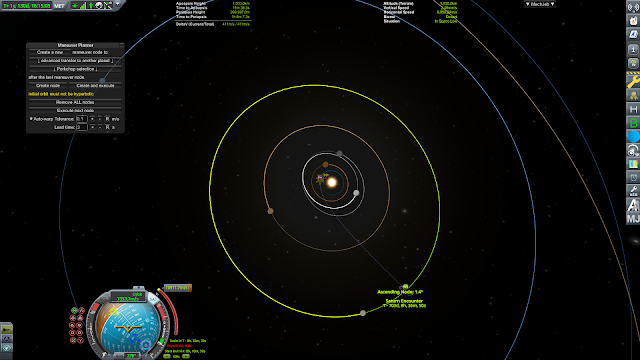 If we had a Starship Lite sitting ready, we could have done it in just over 24 months.Uranus and Neptune will always take a long time to get to, as they are 19.2 and 30.1 AU from the Sun respectively. Voyager 2, the only probe to visit both planets, took 8 years and 5 months to fly past Uranus and a full 12 years to pass Neptune.
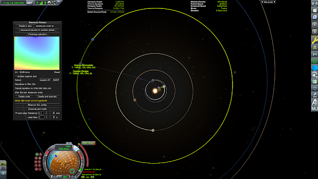
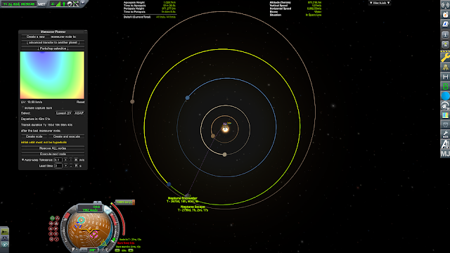 Our faster trajectories mean a 4 year trip to Uranus and 7.5 years to Neptune. These long durations simply mean that chemical propulsion, even on the scale enabled by SpaceX vehicles, is not enough to cross over to the Outer Solar System in reasonable durations. It is much more likely that a good portion of the probe’s mass would be dedicated to electric rockets with high Isp that can shorten the trip and brake at the other end.Mars Express
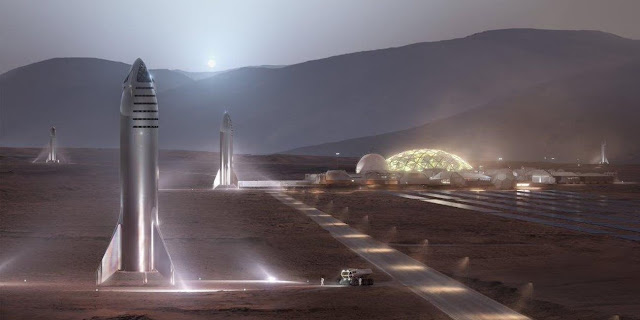 Elon Musk’s dream is Mars. Just how quickly could we get to Mars using the Starship Lite?It will depend of course on the payload we select for the mission. We also want to recover and reuse the Starship vehicle. Previous calculation assumed that once the payload separated from the vehicle, it would carry on into interplanetary or interstellar space, empty and discarded. Regular travel to Mars means that we would have to keep enough fuel in reserve to brake it into an orbit where it can be met by refuelling tankers.One complication with using the Starship Lite instead of the regular Starship is that it does not have any features that allow it to aerobrake. No heatshield, no wings and no fairings means it must rely solely on its own propellants.Let’s work out two scenarios: 10 ton fast, 10 ton staged and 10 ton ultrafast.In the 10 ton fast scenario, we have as the name suggests a payload of 10 tons. The dry mass of the Starship Lite is therefore 40+10: 50 tons. We work out a mass ratio of 24.2 and a deltaV capacity of 11.9km/s.
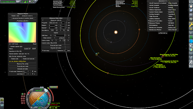
 When using 4.6km/s to leave a 1000km altitude Low Earth Orbit and 6.8km/s to brake into a ~31,000km altitude High Mars Orbit, we get a trip time of 120 days. The total deltaV is 11.5km/s.In the 10 ton staged scenario, the payload is separated from the Starship Lite before it starts its braking burn. This allows the payload to perform an aerobraking or aerocapture maneuver while the Starship brakes while 10 tons lighter.
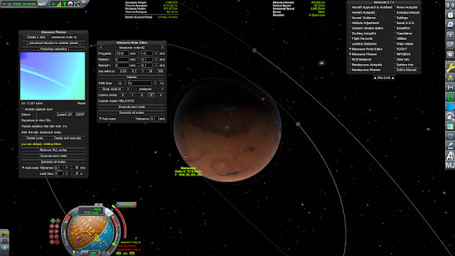 It is possible to accelerate by 5.36km/s leaving Earth to reach Mars in 95 days. After detaching from its payload, the Starship Lite can use its remaining 7.2km/s of deltaV to brake into a 170x800km Low Mars Orbit.The 10 ton ultrafast trajectory consumes the Starship Lite, because we are entering the atmosphere. The payload stages and performs an aerobrake or aerocapture maneuver, just like in the staged scenario, but the Starship Lite burns up alongside it.
 By not having to reserve any propellant for braking, we can take the most energetic trajectory possible. We find that using the full 11.9km/s deltaV capacity it has allows for a trip as short as 47 days.The only caveat is that we must hope the payload’s heatshield can withstand an entry into the Martian atmosphere at over 19km/s!ConclusionThe Starship Lite would be an amazing booster for sending off probes to all of the Solar System’s planets with much reduced travel times, or carrying significant payloads to destinations rapidly. In the most energetic trajectories, it proves itself to be a true Star ship.
 -
On 5/25/2019 at 1:23 AM, 4x4cheesecake said:
The mod is based on this webapp: https://alexmoon.github.io/ksp/
So if you don't expect any ingame features like setting an alarm, this is the way to go
")
Thank you!
-
Hi!
I'm sorry if this has been asked before.
Is these any way to run this calculator outside of KSP?
-
This is from the latest Toughsf blog post: http://toughsf.blogspot.com/2019/05/actively-cooled-armor-from-helium-to.html
Actively Cooled Armor: from Helium to Liquid Tin.
We have seen designs for long ranged particle beams and powerful lasers. Could they be the end-all, be-all of space warfare? Not if we fend off their destructive power with actively cooled armor. Let's have a look at the different cooling solutions, from high pressure gas to liquid metal, and evaluate their relative effectiveness.
Armor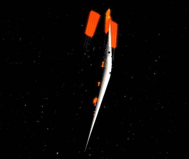
The armor curves away to hide the radiators from attack from the front. The traditional solution for defeating directed energy weapons such as particle beams and lasers is to use solid plates of armor. The armor material would ideally have a high heat capacity so that it doesn't heat up too quickly, and an excellent melting or boiling energy.Graphite excels in both. It is clearly superior when compared to steel or aluminium.We have written about the effectiveness of graphite when facing laser beams, and how we can use different techniques such as sloping, rotation and reflective surfaces to further increase the energy required to remove armor.However, certain techniques described in Lasers, Mirrors and Star Pyramids have limitations. Reflectivity in particular cannot be counted upon in all situations. While we might have broadband dielectric mirrors that effectively reflect a vast range of wavelengths, an enemy will eventually field lasers specifically meant to defeat them.They might select polarizations against which the mirror is less effective, they might use beams of wavelengths too short to reflect (usually below 200nm), or even replace lasers with particle beam weapons that ignore surface features entirely. What can we do against such mirror-defeating techniques? Can we increase the effectiveness of armor even further than what was calculated in Lasers, Mirrors and Star pyramids?Maximizing that energy value means you can get by with less armor and have more mass dedicated to winning tools such as propulsion or ammunition.Passive armorWe can start with a reference to compare everything else to.Passive armor is simple in design and construction. It is made to handle as much heat as possible and prevent it from leaking into the spaceship.
A good example, as mentioned above, is graphite. It first needs to be heated to about 3500K before it starts being degraded. At 4000K, it turns into a gas. Between its heat capacity and vaporization energy, it takes roughly 60 MJ/kg to vaporize. A stronger carbon-based material would take an equivalent amount of energy while also being physically strong.
Graphite electrodes in an electric arc furnace. We can therefore expect graphite to handle a laser intensity of 8.5 MegaWatts per square meter for extended periods of time. This is a value calculated from the Stefan Boltzmann blackbody radiation equation, as it is the intensity required for a black surface to sit at an equilibrium temperature of 3500K.For the laser beam to start digging into the carbon at an appreciable rate, it must first overcome a 14.5 MW/m^2 threshold so that the temperature rises to 4000K, then it must add 60 MJ for each kilogram of carbon to be vaporized.We mentioned active cooling. Being able to remove 11 MW/m^2 using a coolant looping through the armor material significantly raises the damage threshold. In this case, it is increased to 19.5 and 25.5 MW/m^2 respectively.Two other techniques covered in Lasers, Mirrors and Star Pyramids are valid in all situations: sloping and rotating.We can add a good compound slope to the carbon surface: 80 degrees vertical and 67.5 degrees horizontal. This spreads the laser beam over a surface area about 15 times greater. Consequently, the laser now needs to reach an intensity of at least 292.5 MW/m^2.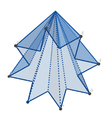 Rotation spreads the beam further. We could have a situation where the beam diameter is 12.56 times smaller than the armor’s circumference, and the average beam intensity is reduced by the same factor.All in all, carbon materials can survive 3.67 GW/m^2 for long periods of time or 4.8 GW/m^2 while ablating.If we have a 100 MW laser with a wavelength of 450nm, being focused by a 4 meter wide mirror, we would be able to damage a simple layer of carbon at a distance of 27,025 km. Using all the techniques just mentioned, the range is shortened to 1,300 km.Why shorten ranges?At very long ranges, space battles are boring with little room for tactical decisions.
We cover this issue in The Laser Problem: any moderately powerful laser can render maneuvers pointless. Warships cannot escape beam weapons. Even at distances where light lag becomes significant, the beam can be divided to cover a wider area while maintaining its destructive intensity.
From here. Shorter ranges allow for acceleration to matter more. Other weapon systems that do not have the supreme range of lasers and particle beams can come into play, such as missiles and kinetics. Angular separation starts to matter, allowing for flanking attacks against warships forced to be more well-rounded to fend off multiple weapons from different directions.It is also important from a narrative and visual perspective. Actions taken have a more immediate effect. Events happen quicker and the danger or relief is greater. It is easier to depict battles and the faster pace will be more agreeable to viewers.Actively cooled armorThe 1,300 km figure given in the previous example is situational.It relies on the beam coming in from an ideal angle, which is straight down the edges of the star pyramid shape. If instead it came from a flanking angle, perhaps 80 degrees from the front, then the vertical slope of 80 degrees is completely negated. The benefit from sloping falls from a factor 15 to just 2.6, which makes the laser effective from a distance (15/2.6)^0.5: 2.4 times greater.In other words, a warship that sustain laser fire from the front at 1,300 km is vulnerable to flanking attacks out to 3,122 km.The benefit from rotation also varies with distance, as it changes the size of the beam’s spot relative to the target’s circumference.- Intensity reduction by rotation = Beam spot radius / (3.142 * Armor radius)
Beam spot radius and armor radius are in meters.The beam spot radius decreases linearly as the distance decreases.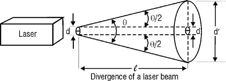
If the warship is being shot at a distance two times closer, then the benefit from rotation is twice as great. This inverse relationship means significant gains from rotation at close distances and small gains at long distances.
Distances, mirror sizes, beam wavelength, warship radii and even spot shapes are all variable, so we are unlikely to ever have one single number to describe the effect of rotation.What technique instead can we rely upon in all situations? Can we increase armor effectiveness without the enemy having to sit in certain positions and relative angles?Active cooling is the solution.We looked at figures of 11 MW/m^2 being removed by flowing water over hot surfaces. Further research shows fusion diverters and rocket engine chambers surviving 100 MW/m^2.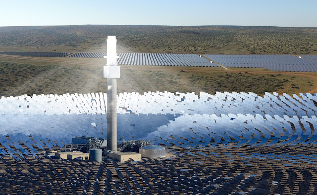 We can go further, to absorb much more power.For the sake of comparison, we will be using a standardized model where a flat plate of armor sits under the glare of a laser beam. It conducts heat through a heat exchanging surface to a coolant flow underneath. The armor is 1cm thick and the coolant flow channel 1cm wide. We will calculate the power required to pump coolant to a certain velocity, and won’t allow velocities that cause turbulence in liquid or supersonic compression in gases. The heat is radiated away using simple 1mm thick carbon fiber radiators.There are fourth factors to consider for a proper comparison. The first is the heat that can be removed per square meter. The second is the pumping power requirement. The third is battle damage resistance, which is not as straightforward. The last is the radiator surface area required to handle the heat.We won’t be working out the effect of thermal conductivity as in most cases it is not the limiting factor.Gas cooled armor
Gases are an interesting coolant as they have no upper temperature limit. If the armor material is carbon and it can withstand a 3500K temperature, then we can select any gas and heat it up to that temperature in the heat exchanger.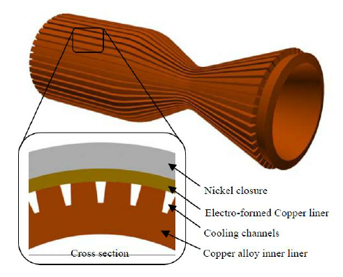
Gas cooled rocket nozzle We are looking for the gas with the highest heat capacity. High heat capacity means less gas needs to flow through the heat exchanger to pick up the heat and carry it away. Less gas means reduced pumping power. We also want a gas that doesn’t condense at lower temperatures.Hydrogen is the best. However, it is reactive. It will chemically reduce the carbon and degrade it. Helium is a second-best alternative that is chemically inert. We want it entering the armor at 500K, heating up to 3500K and exiting to be cooled in a radiator back down to 500K. If it does not reach the desired temperature in one pass through the heat exchanger, it can be recirculated through at the cost of doubling the pumping power.The speed of sound in helium at 500K is 1315m/s. At 3500K, it is 3480m/s. We are limited to pumping below the smaller figure, so let’s give it Mach 0.9 (1183m/). This means we can push 1.13 kg/s under each square meter of armor at 1 bar of pressure, and 28.25 kg/s at 25 bar.Helium absorbs 5.19 kJ/kg/K. Over a temperature rise of 500 to 3500K, 28.25 kg/s will absorb 439.7 MW/m^2.Pumping power requirement depends on the pressure drop across the heat exchanger. It will be the highest of all designs considered in this post.The radiators happily handle the heat using 4994 m^2 and 5 tons of mass.
Gaseous cooling has the advantage that it can increase its performance with increased pumping pressure, and can maintain some degree of functionality while sustaining battle damage. A sudden increase in temperature is not so dangerous as pressure build-up can be vented into space.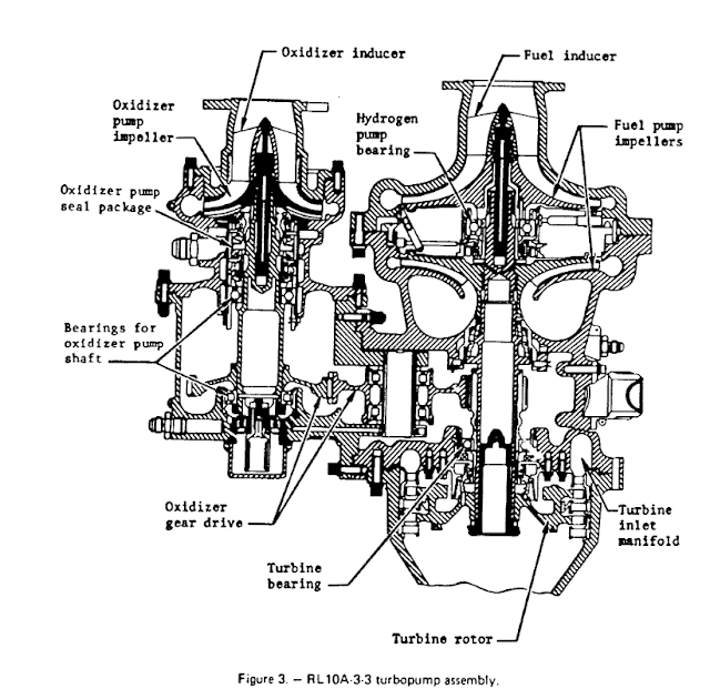
Pumps will most likely resemble those of rocket engines. However, they have the highest pumping power requirements. While we are ignoring thermal conductivity in our calculations, gaseous cooling using helium has the lowest thermal conductivity of all the fluids we will be considering. This imposes certain design restrictions on the heat exchanger interface with the gas, which is trouble when we want the gas to be flowing through it at near Mach speeds.Metal vapor cooled armorHelium has high heat capacity but low density. We need a lot of pumping power to push enough volume through the heat exchanger to draw a decent amount of heat away.
The gases with the highest densities are metal vapours. The same volume brings a lot more mass throughput and therefore cooling capacity.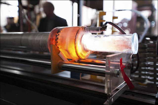
Metal vapour prepared for use as a lasing medium. We want a metal that is dense but boils easily. Mercury is ideal. It boils at 630K, so we’ll set the minimum temperature to 750K to prevent it condensing back into a liquid. As before, we heat it up to 3500K.
The average density of a mercury vapor at 25 bar, between 750 and 3500K, is 48.7 kg/m^3. It would have a heat capacity of 104 J/kg/K and a speed of sound of 227 m/s at 750K. Putting all this together, we expect to push 99.5 kg/s through the 1cm wide heat exchanger and extract 28.5 MW/m^2. This is a much lower performance than with.
Boiling mercury. Pumping requirements are a significantly lower. It is estimated that mercury vapours remove 5 kW of heat from the armor for every watt of pumping power, which is about 20% better than for helium. Only 1563 m^2 of radiators weighing 1.6 tons are needed to handle the heat.The reduced pumping requirements means that you can use many smaller pumps to push the mercury gas through heat exchangers, which helps with redundancy. However, a sudden pressure drop from holes created in the armor are likely to cause the mercury to suddenly expand, cool and revert to its liquid form. The droplets would quickly block gas flow through narrow channels in the heat exchanger.Another difficulty is that mercury can solidify completely behind unheated or damaged armor. Re-establishing a coolant flow is impossible unless the mercury is boiled again to clear the heat exchanger’s channels. Armor would have to ‘go hot’ before battles and prevented from cooling down too much when not under beam attack.Water cooled armorThe traditional cooling liquid is water. It is much denser than a gas, has good thermal conductivity and very high heat capacity.Water’s temperature range is its main limit. If we use it as a liquid, we impose that we use very low temperatures to reject heat from the radiators. Consequently, huge radiating areas would be needed. If we use it as a gas at the same temperatures as helium or metal vapours, it will corrode the heat exchanger and chemically attack everything it touches.Instead, we use a phase change design. High pressures allow water to stay liquid beyond the standard 373K boiling point. It is then heated into steam, up to the maximum temperature the heat exchanger can handle without corrosion. After passing through the radiators, it condenses back into water.
At 25 bar, we can retain liquid water at 480K. That will be our minimum temperature. It has a density of 1197 kg/m^3. We find steam turbine coatings such as chromium steel able to resist 873K steam for thousands of hours, or chromium-niobium alloys at 923K. That will be our maximum temperature. Steam has an average heat capacity of 2.56 kJ/kg/K between 480 and 920K.
The complicated phase diagram of water. The phase change from liquid to gas also absorbs energy. For water, this is a whopping 1840 kJ/kg when starting from 480K.Adding the heat absorbed by the phase change and then rise in temperature, we obtain a total of 2966 kJ/kg.We cannot allow turbulent flow through the heat exchanger, as this drastically decreases the heat transfer rate. Based on a fluid’s Reynolds number and viscosity, we can estimate the maximum velocity before the start of turbulent flow. In this case, it can only be 24 m/s when passing through a 1cm gap.With that flow rate, we get as much as 286.8 kg/s passing through the heat exchanger removing 850 MW/m^2.This is impressive performance. The pumping power requirements are drastically lower than any gas (on the order of 2 kW of heat removed per watt of pumping power). Water has the advantage of gaining most of its heat removing capacity through its phase change when cooling armor from as low as 373K. Increasing the temperature of the armor and therefore of the heat exchanger only improves performance.Another advantage is that it is likely to serve a second role as propellant on spacecraft. Electric, nuclear and solar rockets can all use water. The consequences are that the coolant needed for the armor’s active cooling does not have to be dead weight, and that after being heated into steam, it can be pushed through a nozzle instead of passed into radiators. During battle, if radiators are hidden or destroyed, the armor can still be kept cool by using water as an open-cycle coolant. There are downsides though. Water increases in volume over a thousand-fold between liquid and gaseous states. Designing a phase change heat exchanger where liquid enters one side and gas exits the other is tricky to do, and is unlikely to work after receiving battle damage. In fact, creating a hole in the heat exchanger would release pressure and allow the water entering as a liquid to suddenly boil and practically explode in the pipes.Just like mercury, water can freeze into ice when not heated. Damaged pipes can see themselves blocked by this ice, cutting further cooling. Thankfully, the phase change from liquid into solid also takes a lot of energy, so there is usually plenty of time to re-heat the water and get it flowing again.
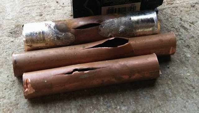 The biggest disadvantage is the maximum temperature restriction on the armor and heat exchanger. Above 920K, the thin layer of water or steam in contact with the heat exchanger starts corroding the protective layer quickly.If the armor is at 3000K, it will be superheating a small quantity of steam to a vigorous oxygen-hydrogen plasma, even if the average temperatures within the heat exchanger as within bounds. Therefore, if the laser intensity overwhelms the cooling capacity and the armor starts heating up to higher temperatures, we will start to see degraded heat exchangers and a decrease in cooling capacity. This is a self-reinforcing cycle that destroys the armor.
 Eutectic cooled armor
Liquid coolants have much reduced pumping power requirements. Instead of water with its restrictive temperature limitations, we might select a coolant that can handle much temperatures.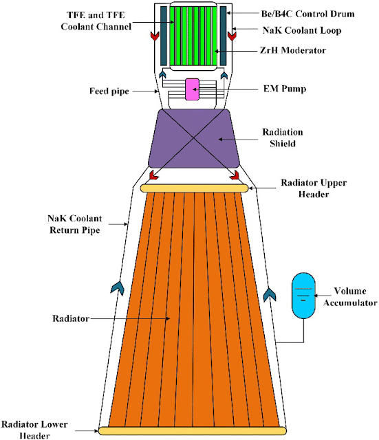
Sodium-Potassium coolants for use in TOPAZ-II space reactor.
Eutetics are mixtures of two or more elements that have a lower melting point than either pure element. A prime example is sodium and potassium used as ‘molten salt’ coolant in nuclear reactors or solar energy storage facilities. Sodium and potassium melt at 371K and 337K respectively, but their eutectic mixture melts at just 260K.
NaK properties.
We will be using Galinstan. It is a mixture of gallium, indium and tin. It melts at 254K and boils at 1573K. With a density of 6440 kg/m^3, a heat capacity of 296 J/kg/K and a laminar flow velocity of 85m/s, we find that we can remove 1738MW/m^2 while radiating away heat at 500K.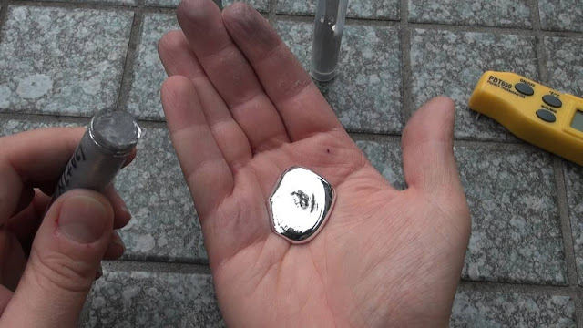
Looks a lot like mercury, but not toxic. From here. This incredibly performance is possible due to the fluid’s high density and high viscosity. Pumping requirements will be significant, and you’d need 490,606 m^2 or 491 tons of radiators for every square meter of armor receiving this intensity, but it is worthwhile when it can reduce ranges by so much.
A note on the radiator requirements: this number is not to be used simply as it is presented. 490,606m^2 are only needed if the enemy beam covers an entire square meter with 1738 MW of power. It is much more likely that a much less powerful beam, for example 100 MW, is focusing its power onto a small spot, perhaps 27cm wide. This gives the same intensity (1738 MW/m^2) but the total heat that must be handled is only 100 MW. The radiator area needed to handle the heat is just 28,218 m^2.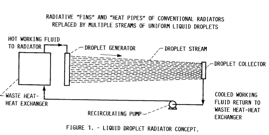
Galinstan would work perfectly inside a liquid droplet radiator. One advantage of Galinstan is that it remains liquid at very low temperatures, so there is a much reduced risk of it solidifying and blocking cooling channels. Another is that as an electrically conductive mix of metals, we can use electromagnetic pumping that can end up being more efficient and more damage resistant than conventional pumps.The main disadvantage is that lasers or particle beams can strike multiple spots along an armor surface without warning, so the coolant flow much be able to compensate for any heating across its entire surface. In other words, the pumps must consume large amounts of power to keep Galinstan flowing across the entire armor surface!Another challenge is when beam intensity overwhelms cooling capacity. 1573K is a decently high boiling point, but it is still lower than the 3500K that carbon materials can handle. A hot spot can create vapor bubbles in the Galinstan flow that could cause destructive cavitation or blocked flow in small channels of a hat exchanger.Liquid metal cooled armorThere are liquids that can handle much higher temperatures without boiling. Liquid metals have the highest boiling points.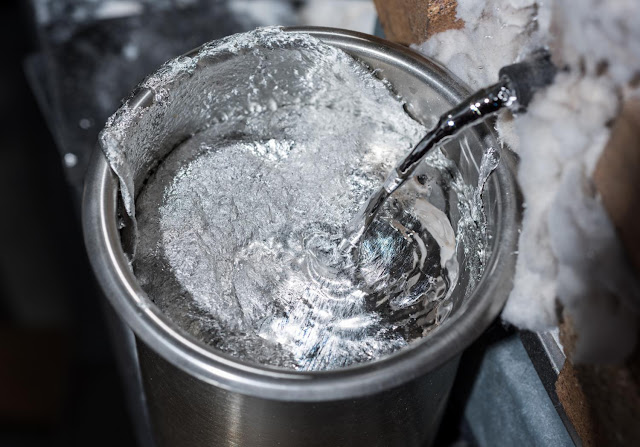 To be a good coolant, we could use a metal with a fairly low melting point, a very high boiling point and the best heat capacity possible. There are many good choices, including plutonium, but we will look at these four in particular: tin, indium, aluminium and cerium.
Indium has a melting point of 430K and a boiling point of 2345K. It has a density of 7020 kg/m^3 and a heat capacity of 233 J/kg/K. We work out that 2944 MW/m^2 can be removed between 500K and 2300K.Tin has a melting point of 505K and a boiling point of 2875K. It has a density of 6990 kg/m^3 and a heat capacity of 228 J/kg/K. We work out that 3666MW/m^2 can be removed between 550 and 2850K.Aluminium has a melting point of 934K and a boiling point of 2792K. It has a density of 2375 kg/m^3 and a heat capacity of 896 J/kg/K. We work out that 3767 MW/m^2 can be removed between 980 and 2750K.
Cerium has a melting point of 1071K and a boiling point of 3697K. It has a density of 6550 kg/m^3 and a heat capacity of 192.4 J/kg/K. We work out that 2999 MW/m^2 can be removed between 1120 and 3500K.For all of the calculations, we limited the flow velocity to 100m/s, despite maximum laminar flow velocities reaching double and more. This gives a more plausible 1m^3 per second volumetric flow rate.
The performance of liquid metal cooled armor far exceeds that of other cooling solutions.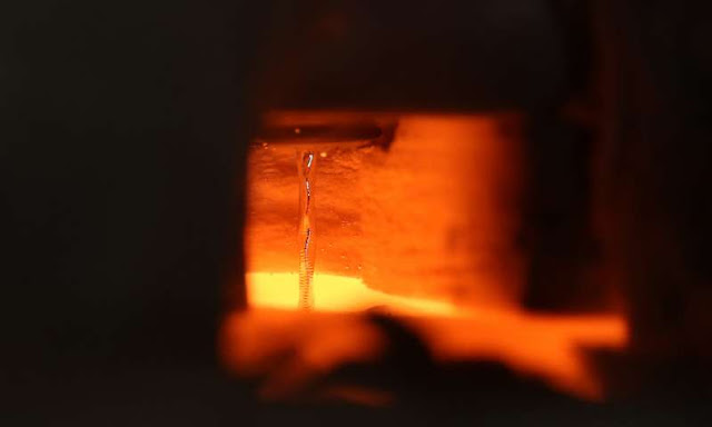
We have ceramic pumps that can handle liquid metals, and we go further. Indium is at the lowest risk of solidifying in the pipes, but has the highest pumping requirement and imposes the lowest temperature limit on the armor.Aluminium provides the best performance and the lowest pumping power requirement, but it is the most reactive of the metals and so needs a protective layer in between it and the carbon armor.Cerium, with its very high boiling point, is unlikely to ever create vapour bubbles in the heat exchanger and has the smallest radiators, but it is also at the greatest risk of solidifying inadvertently.Tin is the overall best choice.The danger of course is that a battle starts with the tin in its solid state. Directed energy weapons could add heat to an armor plate too quickly for the tin to melt and start flowing to draw it away. Ideally, the tin is constantly flowing at the minimum temperature, which is 550K in this case. For efficiency’s sake, it could be kept molten using waste heat from a nuclear reactor. However, pumping the metal would consume electrical power that has to be taken away from other systems.
Spaceship designers could make use of the armor layer as another radiator. It would be durable and usable even in battle. Other than the sections under laser attack, it could be rejecting up to 3.5 kW of waste heat for each square meter sitting on liquid tin. This feature could compensate for the extra heat from a nuclear reactor that needs to operate at a higher power level to feed the pumps with electricity.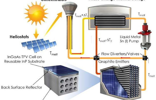
Liquid tin as a thermal transport coolant to a solar energy storage system. Reduced beam rangesLet’s work out the effective range of a beam weapon facing a carbon armor layer using all the tricks available to us: rotation, compound sloping and active cooling.As before, we set the weapon to be a 100 MW laser of 450nm wavelength, being focused by a 4m wide mirror.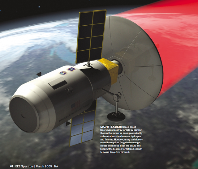 The target will an eight-pointed star (octagram) pyramid 6m wide at the base and 17.3 meters long. This gives it a vertical slope of 80 degrees and a horizontal slope of 67.5 degrees. Each face of the octagram is 1.76m long, which means a total circumference of 28.1m.Before combat, the armor maintains a flow of liquid tin through it. It serves as a radiator which handles about 1.26 MW of heat on its own.During combat, 3.6 GW/m^2 can be absorbed when the liquid tin gets really hot. The maximum temperature we’ll allow is 2800K to prevent any hotspots from boiling the tin. The heated carbon also radiates another 3.5MW/m^2, but this is a tiny contribution.An enemy attacking the pointy end of the star pyramid would face a compound slope that spreads their beam over a surface area 15 times greater. This is a 15-fold reduction in intensity. Working it out, the armor can handle 54.2 GW/m^2 with ideal sloping. If the enemy attacked from the side, they would face only the horizontal slope that reduces intensity by 2.6-fold. The armor can only handle 9.4 GW/m^2 in that case.We can see already that the intensities the armor can handle are much greater than in previous examples.The laser we are considering can only produce an intensity of 9.4 GW/m^2 at distance of 812.6 km. If our warship is outnumbered, it would want to stay at least this distance away from its closest opponent.54.2 GW/m^2 is only possible at a distance of 338.4 km. Our warship can get this close if it is confident that it can always face its pointy end to the enemy.What about rotation?In these scenarios, the benefits could be massive. At 338.4km, the spot radius of the laser is 2.4cm, and at 812.6km, it is 5.8cm. These are 1170.8x and 484.5x smaller than the circumference of our armor. In ideal conditions, it is a reduction in intensity of 1170.8x and 484.5x. A supremely confident commander could bring our warship to single-digit kilometres in front of the beam and expect to spread its power enough to never overwhelm its cooling capacity!There are important consequences for this sort of cooling capacity and reduction beam ranges. Many depend on the specifics of the setting where space warfare takes place.
In general though, we can reasonably expect that battles will revolve around achieving a flanking position, suppressing the cooling capability of the armor or preventing electrical generation that powers the pumps. The latter two objectives can be achieved by pulsed lasers, penetrating particle beams, kinetic strikes and other weaponry that are not continuous beams.
Laser attack, captured and edited from this Children of a Dead Earth video. At the very least, the threat of giant laser-equipped warships and their dampening effect on any sort of eventful space combat can be reduced or eliminated in science fiction. -
On 4/23/2019 at 8:00 PM, DDE said:
Yes! Finally! A topic that I could never really sink my teeth into, despite encountering quite a few non-spurious references to it.
Thanks for the follow, BTW.
I followed for your excellent post on the RD-600 russian gas-core rocket.
On 4/24/2019 at 9:40 AM, KerikBalm said:So, they mention Uranium Flouride quenching... Would it be any better if one was using Thorium? as in a breeder reactor? Most of the fuel elements would be thorium 232, and Uranium 233 would be consumed shortly after being produced (so there is very little uranium at any given time)... could that help, or would the thorium quench just about as much as the Uranium?
The quenching comes from the interaction between the photons generated by the lasing medium and the massive cloud of electrons surrounding an atom like uranium. Thorium, with 90 electrons, will very likely have the same quenching effect as Uranium, with 92 electrons.
-
3 hours ago, magnemoe said:
Note that an solar panel designed for an laser will be close to 100% efficient. You would still need cooling but its an nice way to drive an ion engine probe.
Star shot missed the mark.
Yes you can push 10 grams to 0.1c but I rater want some ton in Uranus orbit asap.Only when cooled, and only up to 70%
Look at this document: http://epubs.surrey.ac.uk/841789/1/Scott_Jarvis_Final_Thesis_280717.pdf
With a powerful laser, you can just use a laser-thermal propulsion system. Even more lightweight and with greater overall efficiency than with intermediate electrical conversion steps. It has also been proven at 5000s Isp: http://toughsf.blogspot.com/2017/03/laser-launch-into-orbit.html
-
-
6 hours ago, wumpus said:
One thing you never did was show how much momentum per Watt you get out of a photon, and compared that to an ion being flung into space. You need a unbelievably efficient process to begin to make sense.
Why a laser? It seems that ordinary luminescence would be more efficient. You don't need to focus the light all that well, just enough to get going in the right direction. Is a laser needed to handle the concentration of energy in space? I understand most of the research was for lasers, but that doesn't mean that they make the best means for an engine.
Blackbody radiation will be used regardless of the interstellar propulsion method. Also expect to eventually align your radiators perpendicular as speeds go relativistic (presumably half pointing each way) to travel, just to avoid the constant high-energy bombardment from interstellar hydrogen hitting your radiators.
The direct thrust from a nuclear reactor laser is too small to matter. Because of this, a photonic propulsion system was not proposed or discussed in the blog post or the text I copied. Instead, the laser is used as a weapon or to beam power over long distances.
You can estimate the acceleration from the power density. 1kW/kg gives an acceleration of 2.26 nanogees.
-
This is from Nuclear Reactor Lasers: from Fission to Photon: http://toughsf.blogspot.com/2019/04/nuclear-reactor-lasers-from-fission-to.html
Nuclear Reactor Lasers: from Fission to Photon
Nuclear reactor lasers are devices that can generate lasers from nuclear energy with little to no intermediate conversion steps. We work out just how effective they can be, and how they stack up against conventional electrically-powered lasers. You might want to re-think your space warfare and power beaming after this.Nuclear energy and space have been intertwined since the dawn of the space age. Fission power is reliable, enduring, compact and powerful. These attributes make it ideal for spacecraft that must make every kilogram of mass as useful and as functional as possible, as any excess mass would cost several times its weight in extra propellant. They aim for equipment for the highest specific power (or power density PD), meaning that it produces the most watts per kilogram.
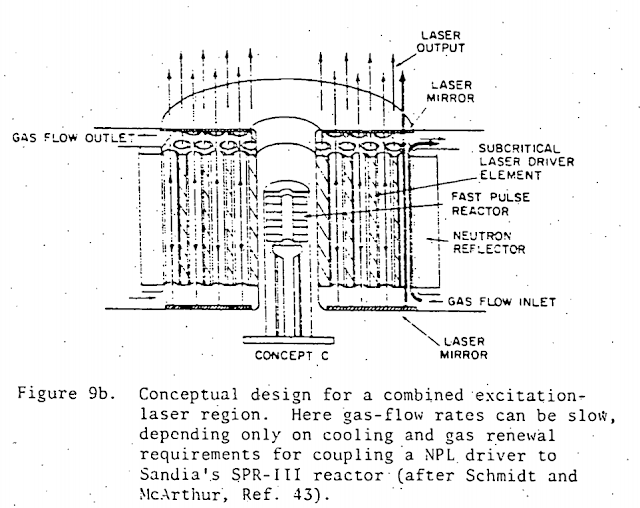 Lasers use a lasing medium that is rapidly energized or ‘pumped’ by a power source. Modern lasers use electric discharges from capacitors to pump gases, or a current running through diodes. The electrical power source means that they need a generator and low temperature radiators in addition to a nuclear reactor… these are significant mass penalties to a spaceship.
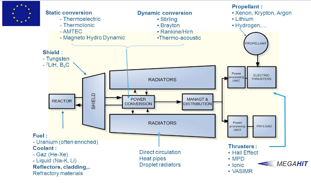 Fission reactions produce X-rays, neutrons and high energy ions. The idea to use them to pump a lasing medium has existed ever since the first coherent wavelengths were released from a ruby crystal in 1960.
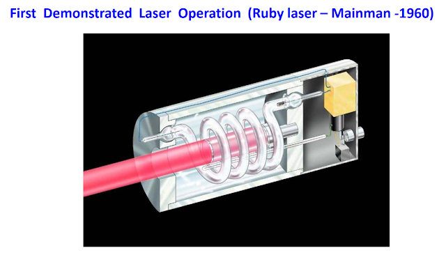 Much research has been done in the 80s and 90s into nuclear-pumped lasers, especially as part of the Strategic Defense Initiative. If laser power can be generated directly from a reactor, there could be significant gains in power density.
 The research findings on nuclear reactor lasers were promising in many cases but did not succeed in convincing the US and Russian governments to continue their development. Why were they unsuccessful and what alternative designs could realize their promise of high power density lasers?Distinction between NBPLs and NRLsMost mentions of nuclear pumped lasers relate to nuclear bombpumped lasers. They are exemplified by project Excalibur: the idea was to use the output of a nuclear device to blast metal tubes with X-rays and have them produce coherent beams of their own.
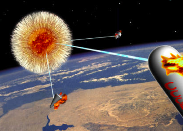 We will not be focusing on it.The concept has many problems that prevent it from being a useful replacement for conventional lasers. You first need to expend a nuclear warhead, which is a terribly wasteful use of fissile material. Only a tiny fraction of the warhead’s X-rays, which are emitted in all directions, are intercepted by the metal tube. From those, a tiny fraction of its energy is converted into coherent X-rays. If you multiply both fractions, you find an exceedingly low conversion ratio.
 Further research has revealed this to be on the order of <0.00001%. It also works for just a microsecond, each shot destroys its surroundings and its effective range is limited by relatively poor divergence of the beam. These downsides are acceptable for a system meant to take down a sudden and massive wave of ICBMs at ranges of 100 to 1000 kilometers, but not much else.Instead, we will be looking at nuclear reactor pumped lasers. These are lasers that draw power from the continuous output of a controlled fission reaction.PerformanceWe talk about efficiency and power density to compare the lasers mentioned in this post. How are we working them out?For efficiency, we multiply the reactor’s output by the individual efficiencies of the laser conversion steps, and assume all inefficiencies become waste heat. The waste heat is handled by flat double-sided radiator panels operating at the lowest temperature of all the components, which is usually the laser itself.
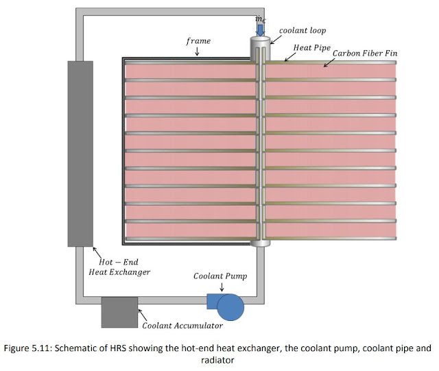 This will give a slightly poorer performance than what could be obtained from a real world engineered concept. The choice of radiator is influenced by the need for easy comparison instead of maximizing performance in individual designs.We will note the individual efficiencies as Er for the reactor, El for the laser and Ex for other components. The overall efficiency will be OE.
- OE = Er * Ex * El * Eh
In most cases, Er and Eh can be approximated as equal to 1. As we are considering lasers for use in space with output on the order of several megawatts and beyond, it is more accurate to use the slope efficiency of a design rather than the reported efficiency. Laboratory tests on the milliwatt scale are dominated by the threshold pumping power, which cuts into output and reduces the efficiency. As the power is scaled up, the threshold power becomes a smaller and smaller fraction of the total power. Calculating power density (PD) in Watts per kg for several components working with each other’s outputs is a bit more complicated. As above, we’ll note them PDr, PDl, PDh, PDx and so on. The equation is:
- PD = (PDr * OE) / (1 + PDr (Ex/PDx + Ex*El/PDl + (1 - Ex*El)/PDh))
Generally, the reactor is a negligible contributor to the total mass of equipment, as it is in the several hundred kW/kg, so we can simplify the equation to:- PD = OE / (Ex/PDx + Ex*El/PDl + (1 - Ex*El)/PDh)
Inputting PDx, PDl and PDh values in kW/kg creates a PD value also in kW/kg.Direct PumpingThe most straightforward way of creating a nuclear reactor laser is to have fission products interact directly with a lasing medium. Only gaseous lasing mediums, such as xenon or neon, could survive the conditions inside a nuclear reactor indefinitely, but this has not stopped attempts at pumping a solid lasing medium.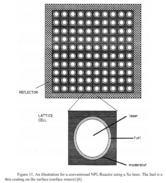 Three methods of energizing or pumping a laser medium have been successful.Wall pumpingWall pumping uses a channel through which a gaseous lasing medium flows while surrounded by nuclear fuel. The fuel is bombarded by neutrons from a nearby reactor. The walls then release fission fragments that collide with atoms in the lasing medium and transfer their energy to be released as photons. The fragments are large and slow so they don’t travel far into a gas and tend to concentrate their energy near the walls. If the channels are too wide, the center of the channel is untouched and the lasing medium is unevenly pumped. This can create a laser of very poor quality.
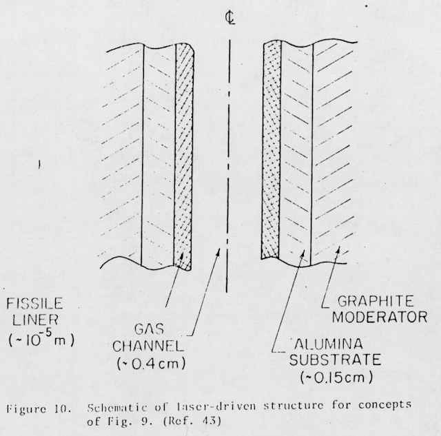 To counter this, the channels are made as narrow as possible, giving the fragments less distance to travel. However, this multiplies the numbers of channels needed to produce a certain amount of power, and with it the mass penalty from having many walls filled with dense fissile fuel.
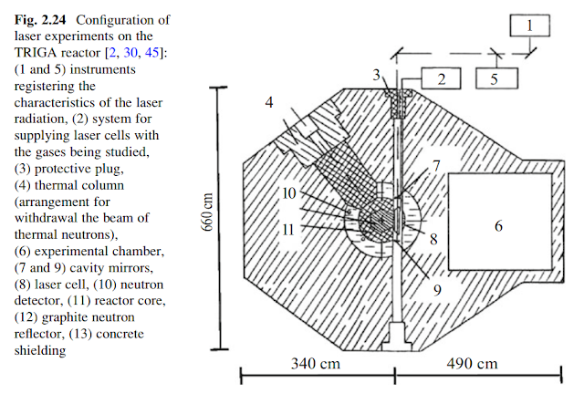 The walls absorb half of the fission fragments they create immediately. They release the surviving fragments from both faces of fissile fuel wall. So, a large fraction of the fission fragment power is wasted. They are also limited by the melting temperatures of the fuel. If too many fission fragments are absorbed, the heat would the walls to fail, so active cooling is needed for high power output.
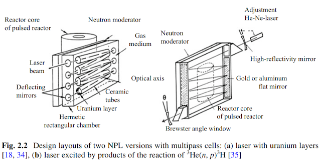 The FALCON experiments achieved an efficiency of 2.5% when using xenon to produce a 1733 nm wavelength beam.
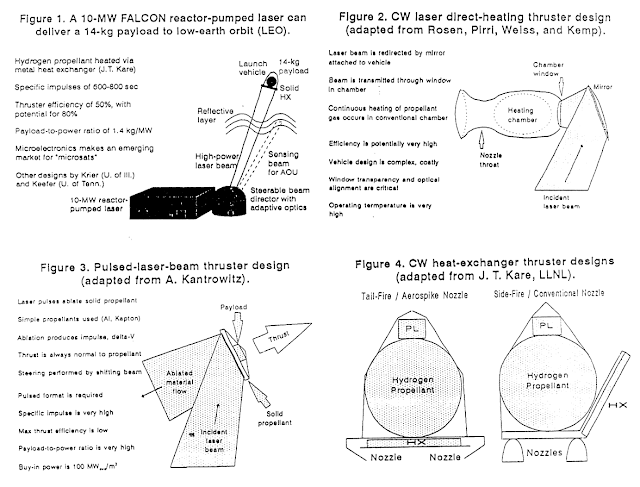 Gas laser experiments at relatively low temperatures reported single-wavelength efficiencies as high as 3.6%. The best reported performance was 5.6% efficiency from an Argon-Xenon mix producing 1733 nm laser light, from Sandia National Laboratory.
 Producing shorter wavelengths using other lasing mediums, such as metal vapours, resulted in much worse performance (<0.01% efficiency).Higher efficiencies could be gained from a carbon monoxide or carbon dioxide lasing medium, with up to 70% possible, but their wavelengths are 5 and 10 micrometers respectively (which makes for a very short ranged laser) and a real efficiency of only 0.5% has been demonstrated.One estimate presented in this paper is a wall-pumped mix of Helium and Xenon that converts 400 MW of nuclear power into 1 MW of laser power with a 1733 nm wavelength. It is expected to mass 100 tons. That is an efficiency of 0.25% and a power density of just 10 W/kg.
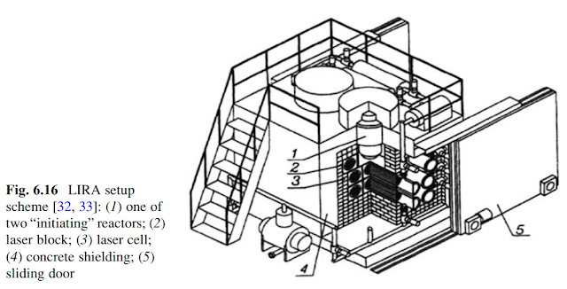 It illustrates the fact that designs meant to sit on the ground are not useful references.A chart from this NASA report reads as a direct pumped nuclear reactor laser with 10% overall efficiency having a power density of about 500 W/kg, brought down to 200 W/kg when including radiators, shielding and other components.
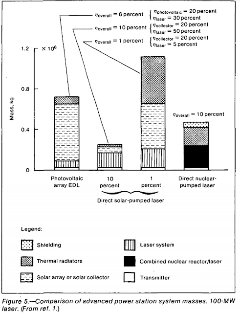 Volumetric pumpingVolumetric pumping has Helium-3 mixed in with a gaseous lasing medium to absorb neutrons from a reactor.
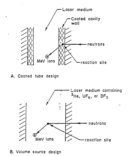 Neutrons are quite penetrating and can traverse large volumes of gas, while Helium 3 is very good at absorbing neutrons. When Helium-3 absorbs neutrons, it creates charged particles that in turn energize lasing atoms when they enter into contact with each other. Therefore, neutrons can fully energize the entire volume of gas. The main advantages of this type of laser pumping is the much reduced temperature restrictions and the lighter structures needed to handle the gas when compared to multiple narrow channels filled with dense fuel.
 However, Helium-3 converts neutrons into charged particles with very low efficiency, with volumetric pumping experiments reporting 0.1 to 1% efficiency overall. This is because the charged particles being created contain only a small portion of the energy the Helium-3 initially receives.Semiconductor pumpingThe final successful pumping method is direct pumping of a semiconductor laser with fission fragments. The efficiency is respectable at 20%, and the compact laser allows for significant mass savings, but the lasing medium is quickly destroyed by the intense radiation. It consists of a thin layer of highly enriched uranium sitting on a silicon or gallium semiconductor, with diamond serving as both moderator and heatsink.There are very few details available on this type of pumping.
 A space-optimized semiconductor design from this paper that suggests that an overall power density of 5 kW/kg is possible. It notes later on that even 18 kW/kg is achievable. It is unknown how the radiation degradation issue could be solved and whether this includes waste heat management equipment. Without an operating temperature and a detailed breakdown of the component masses assumed, we cannot work it out on our own.Other direct pumped designsWall or volumetric pumping designs were conceived when nuclear technology was still new and fission fuel had to stay in dense and solid masses to achieve criticality. More modern advances allow for more effective forms for the fuel to take.
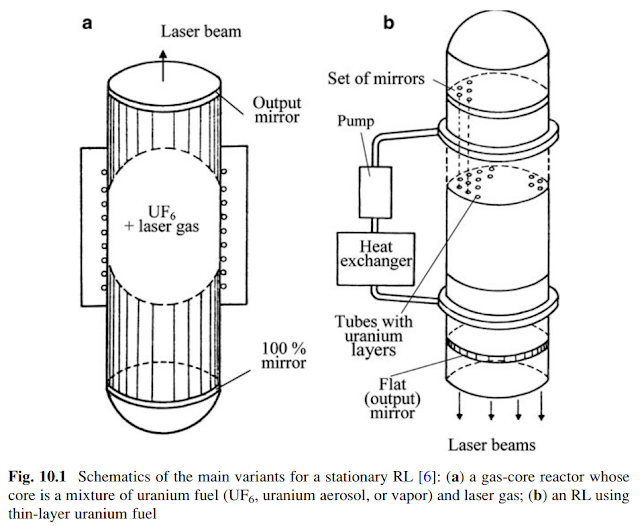 The lasing medium could be made to interact directly with a self-sustaining reactor core. This involves mixing the lasing medium with uranium fluoride gas, uranium aerosols, uranium vapour at very high temperatures or uranium micro-particles at low temperatures.The trouble with uranium fluoride gas and aerosols or micro-particles is the tendency for them to re-absorb the energy (quenching) of excited lasing atoms. This has prevented any lasing action from being realized in all experiments so far. As this diagram shows, uranium fluoride gas absorbs most wavelengths very well, further reducing laser output.
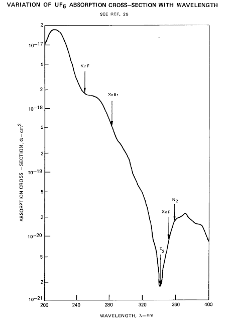 If there is a lasing medium that is not quenched by uranium fluoride, then there is potential for extraordinary performance.
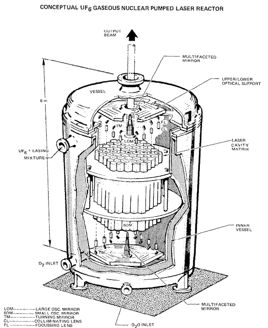 An early NASA report on an uranium fluoride reactor lasers for space gives a best figure of 73.3 W/kg from what is understood to be a 100 MW reactor converting 5% of its output into 340 nanometer wavelength laser light. With the radiators in the report, this falls to 56.8 W/kg.
It we bump up the operating temperature to 1000K, reduce the moderator to the 20cm minimum, replace the pressure vessel with ceramics and use more modern carbon fiber radiators, we can expect the power density of that design to increase to 136 W/kg.
Uranium vapours are another option. They require temperatures of 4000K and upwards but if the problem of handling those temperatures is solved (perhaps by using actively cooled graphite containers), then 80% of the nuclear output can be used to excite the lasing medium, for an overall efficiency that is increased four-fold over wall pumping designs.
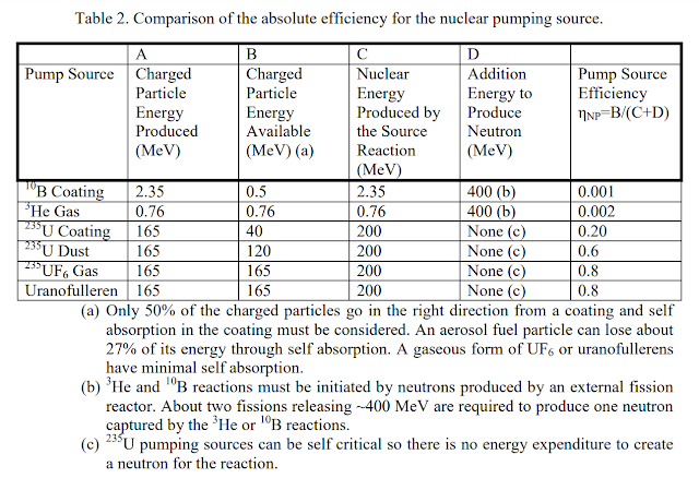 More speculative is encasing uranium inside a C60 Buckminsterfullerene sphere. Fission fragments could exit the sphere while also preventing the quenching of the lasing material. This would allow for excellent transmission of nuclear power into the lasing medium, without extreme temperature requirements.Nuclear-electric comparison
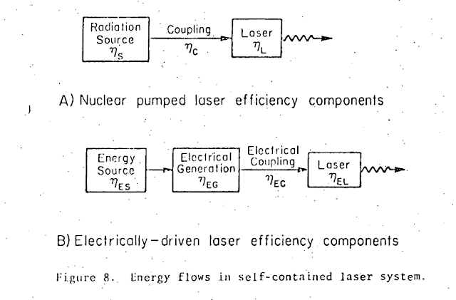 With these numbers in mind, it does not look like direct pumping is the revolutionary upgrade over electric lasers that was predicted in the 60s.Turbines, generators, radiators and laser diodes have improved by a lot, and they deliver a large fraction of a reactor’s output in laser light. We expect a space-optimized nuclear-electric powerplant with a diode laser to have rather good performance when using cutting edge technology available today.
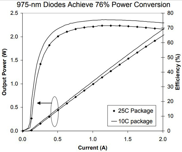 With a 100 kW/kg reactor core, a 50% efficient turbine at 10 kW/kg, an 80% efficient electrical generator at 5 kW/kg, powering 60% efficient diodes at 7 kW/kg and using 1.34 kW/kg radiators to get rid of waste heat (323K temperature), we get an overall efficiency of 24% and a power density of 323 W/kg.
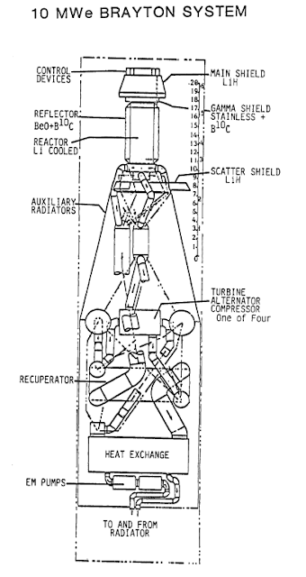 A more advanced system using a very powerful 1 MW/kg reactor core, a 60% efficient MHD generator at 100 kW/kg with 1000K 56.7 kW/kg radiators, powering a 50% efficient fiber laser cooled by 450K 2.3 kW/kg radiators, would get an overall efficiency of 30% and a power density of 2.5 kW/kg.
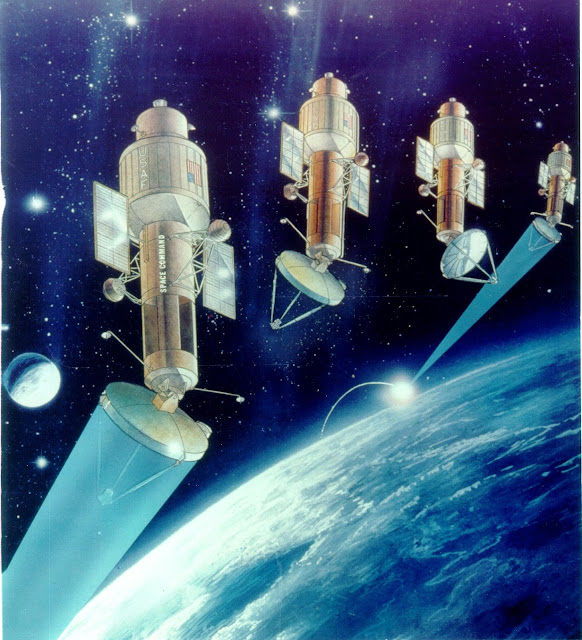 Can we beat these figures with reactor lasers?Indirect pumpingThe direct pumping method uses the small fraction of a reactor’s output that is released in the form of neutrons, or problematic fission fragments. Would it not be better to use the entire output of the nuclear reaction?Indirect pumping allows us to use 100% of the output in the form of heat. This heat can then be converted into laser light in various ways.
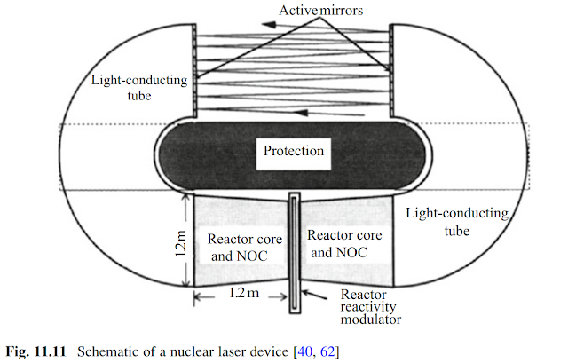 Research and data for some of the following types of lasers comes from solar-heated designsthat attempt to use concentrated sunlight to heat up an intermediate blackbody that in turn radiates onto a lasing medium. For our purposes, we are replacing the heat of the Sun with a reactor power source. It is sometimes called a ‘blackbody laser’ in that case.Blackbody radiation pumpAt high temperatures, a blackbody emitter radiates strongly in certain wavelengths that lasing materials can be pumped with. A reactor can easily heat up a black carbon surface to temperatures of 2000 to 3000K – this is what nuclear rockets are expected to operate at anyhow.
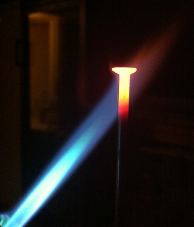 Some of the spectrum of a blackbody at those temperatures lies within the wavelengths that are absorbed well by certain crystal and gaseous lasing mediums.Neodymium-doped Ytrrium-Aluminium-Garnet (Nd:YAG) specifically is a crystal lasing medium that has been thoroughly investigated as a candidate for a blackbody-pumped laser. It produces 1060 nm beams.
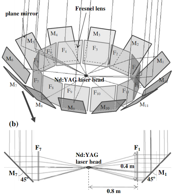 Efficiency figures vary.A simple single-pass configuration results in very poor efficiency (0.1 to 2%). This is because the lasing medium only absorbs a small portion of the entire blackbody spectrum. In simpler terms, if we shine everything from 100 nm to 10,000 nm onto a lasing medium, it will convert 0.1 to 2% of that light into a laser beam and turn the rest into waste heat. With this performance, blackbody pumped lasers are no better than direct pumped reactor laser designs from the previous section.Instead, researchers have come up with a way to recover the 99 to 99.9% of the blackbody spectrum that the lasing medium does not use. This is the recycled-heat blackbody pumped laser.
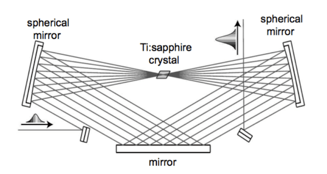 An Nd:YAG crystal sits inside a ‘hot tube’. Blackbody radiation coming from the tube walls passes through the crystal. The crystal is thin and nearly transparent to all wavelengths. The illustration above uses Ti:Sapphire but the concept is the same for any laser crystal.
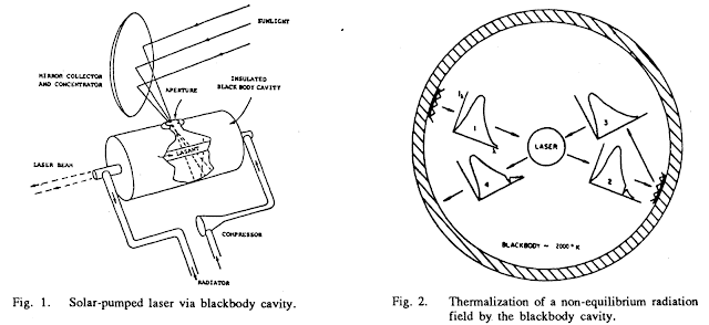 Only about 2% of blackbody spectrum is absorbed with every pass through the crystal. The remaining 97 to 98% pass through to return to the hot tube’s walls. They are absorbed by a black carbon surface and recycled into heat. Over many radiation, absorption and recycling cycles, the fraction of total energy that becomes laser light increases for an excellent overall efficiency.
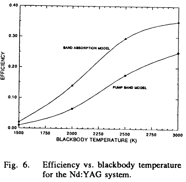 35% efficiency with a Nd:YAG laser was achieved.The only downside is that the Nd:YAG crystal needs intense radiation within it to start producing a beam. The previous document suggests that 150 MW/m^3 is needed. Another source indicates 800 MW/m^3. We also know that efficiency increases with intensity. If we aim for 1 GW/m^3, which corresponds to 268 Watts shining on each square centimetre of a 1 cm diameter lasing rod, we would need a 1:1 ratio of emitting to receiving area if the emitter has a temperature of at least 2622K.
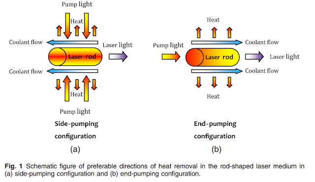 From a power conversion perspective, a 98% transparent crystal that converts 35% of spectrum it absorbs means it is only converting 0.7% of every Watt of blackbody radiation that shines through it. So, a crystal rod that receives 268 Watts on each square centimetre will release 1.87 W of laser light.
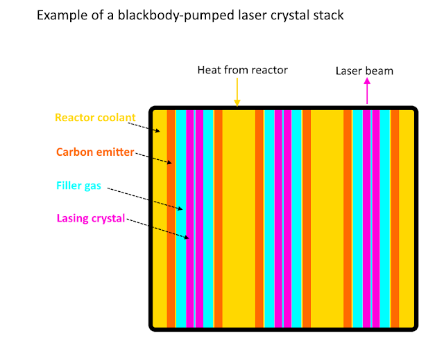 We can use the 1:1 ratio of emitter and receiver area to reduce weight and increase power density. Ideally, we can stack emitter and receiver as flat surfaces separated by just enough space to prevent heat transfer through conduction.Reactor coolant channels, carbon emitting surface (1cm), filler gas, Nd:YAG crystal (1cm) and helium channels can be placed back to back. The volume could end up looking like a rectangular cuboid, interspaced by mirror cavities.20 kg/m^2 carbon layers and 45.5 kg/m^2 crystal layers that release 1.87 W per square centimetre, with a 15% weight surplus for other structures and coolant pipes, puts this component’s power density at about 250 W/kg.
 The laser crystal is cooled from 417K according to the set-up in this paper. Getting rid of megawatts at such a low temperature is troublesome. Huge radiator surface areas will be required.As we are using flat panel radiators throughout this post, we have only two variables: material density, material thickness and operating temperature. The latter is set by the referenced document.We will choose a 1mm thick radiator made of low density polyethylene. We obtain 0.46 kg/m^2 are plausible. When radiating at 417K, they could achieve 3.73 kW/kg.It is likely that they will operate at a slightly lower temperature to allow for a thermal gradient that transfers heat out of the lasing medium and into the panels, and the mass of piping and pumps is not to be ignored, but it is all very hard to estimate and is more easily included in a 15% overall power density penalty for unaccounted-for components.A 100 kW/kg reactor, 250 W/kg emitter-laser stack and 3.73 kW/kg radiators would mean an overall power density of 188 W/kg, after applying the penalty.
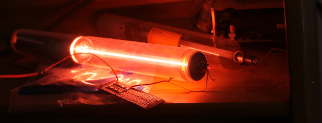 Gaseous lasing mediums could hold many advantages over a crystal lasing medium. They require much less radiation intensity (W/m^3) to start producing a laser beam. This researchstates that an iodine laser requires 450 times less intensity than an equivalent solid-state laser. It is also easier to cool a gas laser, as we can simply get the gas to flow through a radiator. On the other hand, turbulent flow and thermal lensing effects can deteriorate the quality of a beam into uselessness.No attempts have been reported on applying the heat recycling method from the Nd:YAG laser to greatly boost efficiency in a gas laser. Much research has been performed instead on direct solar-pumped lasers where the sunlight passes through a gaseous medium just once.The Sun can be considered to be a blackbody emitter at a temperature of 5850K. Scientists have found the lasing mediums best suited to being pumped by concentrated sunlight – they absorb the largest fraction of the sunlight’s energy.
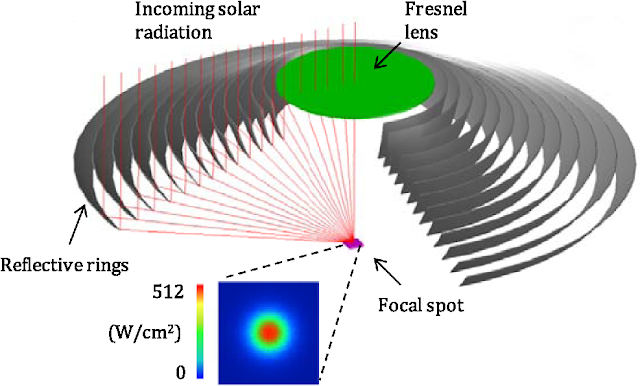 That fraction is low in absolute terms, meaning poor overall performance. An iodine-based lasing medium reported 0.2% efficiency. Even worse efficiency of 0.01% was achieved when using an optically-pumped bromine laser. Similarly, C3F7I, an iodine molecule which produces 1315 nm laser light, was considered the best at 1% efficiency.Solid blackbody emitters are limited to temperatures just above 3000K. There would be a great mismatch between the spectrum this sort of blackbody releases and the wavelengths the gaseous lasing mediums cited above require. In short, the efficiency would fall below 0.1% in all cases.One final option is Gallium-Arsenic-Phosphorus Vertical External Cavity Surface Emitting Laser (VECSEL) designed for use in solar-powered designs. It can absorb wavelengths between 300 and 900nm, which represents 65% of the solar wavelengths but only 20% of the radiation from a 3000K blackbody. This works out to an emitter with a power density of 45.9 kW/kg.
 The average efficiency is 50% when producing a 1100nm beam. Since it is extracting 20% of the wavelengths from the emitter, this amounts to 10% overall efficiency.
 Using the numbers in this paper, we can surmise that the VECSEL can handle just under 20 MW/kg. The mass of the laser is therefore negligible. With a 100 kW/kg reactor, we work out a power density of 3.1 kW/kg.
 VECSELs can operate at high temperatures, but they suffer from a significant efficiency loss. We will keep them at 300K at most. It is very troublesome as 20 MW of light is needed to be concentrated on the VECSEL to start producing a laser beam. 90% of that light is being turned into waste heat within a surface a few micrometers thick. Diamond heatsink helps in the short term but not in continuous operation.Radiator power density will suffer. Even lightweight plastic panels at 300K struggle to reach 1 kW/kg. When paired with the previous equipment and under a 15% penalty for unaccounted for components, it means an overall power density of 91 W/kg.This illustrates why an opaque pumping medium is unsuitable for direct pumping as it does not allow for recycling of the waste heat.Filtered blackbody pumpingA high temperature emitter radiates all of its wavelengths into the blackbody-pumped lasing medium. We described a method above for preventing the lasing medium from absorbing 98 to 99.9% of the incoming energy and turning it immediately into waste heat. The requirement was that the lasing medium be very transparent to simply let through the unwanted wavelengths.
 However, this imposes several design restrictions on the lasing medium. It has to be thin, it has to be cooled by transparent fluids, and it might have to sit right next to a source of high temperature heat while staying at a low temperature itself.
 We can instead filter out solely the laser pumping wavelengths from the blackbody spectrum and send those to the lasing medium while recycling the rest.
 The tool to do this is a diffraction grating. There are many other ways of extracting specific wavelengths from a blackbody radiation spectrum, such as luminescent dyes or simple filters, but this method is the most efficient.
 Like a prism, a diffraction grating can separate out wavelengths from white light and send them off in different directions. For most of those paths, we can put a mirror in the way that send the unwanted wavelengths back into the blackbody emitter. For a small number of them, we have a different mirror that reflects a specific wavelength into the lasing medium.
 A lasing medium that receives just a small selection of optimal wavelengths is called optically pumped. It is a common feature of a large number of lasers, most notably LED-pumped designs. We can use them as a reference for the potential performance of this method.We must note that while we can get high efficiencies, power is still limited, as in the previous section. Extracting a portion of the broadband spectrum that the lasing medium accepts also means that power output is reduced to that portion.Another limitation is the temperature of the material serving as a blackbody emitter. The nuclear reactor that supplies the heat to the emitter is limited to 3000K in most cases, so the emitter must be at that temperature or lower (even if a carbon emitter can handle 3915K at low pressures and up to 4800K at high pressures, while sublimating rapidly).Thankfully, the emission spectrum of a 3000K blackbody overlaps well with the range of wavelengths an infrared fiber laser can be pumped with.
 A good example is an erbium-doped lithium-lanthanide-fluoride lasing medium in fiber lasers. We could use it to produce green light as pictured above, but invisible infrared is more effective.
 As we can see from here, erbium absorbs wavelengths between 960 and 1000 nm rather well. It re-emits them at 1530 nm wavelength laser light with an efficiency reported to be 42% in the ‘high Al content’ configuration, which is close the 50% slope efficiency.In fact, the 960-1000 nm band represents 2.7% of the total energy emitted. It is absorbing 125 kW from each square meter of emitter. If the emitter is 1 cm thick plate of carbon and the diffraction grating, with other internal optics needed to guide light into the narrow fiber laser, are 90% efficient, then we can expect an emitter power density of about 5.6 kW/kg.
 Another example absorbs 1460 to 1530 nm light to produce a 1650 nm beam. This is 3.7% of the 3000K emitter’s spectrum, meaning an emitter power density of 7.7 kW/kg.
 The best numbers come from ytterbium fiber lasers. They have a wider band of wavelengths that can be pumped with, 850 to 1000 nm (which is 10.1% of the emitter’s output), and they convert it into 1060 nm laser light with a very high efficiency (90%). It would give the emitter an effective power density of 23.4 kW/kg. More importantly, we have examplesoperating at 773K.The respected Thorlabs manufacturer gives information about the fiber lasers themselves. They can handle 2.5 GW/m^2 continuously, up to 10GW/m^2 before destruction. Their largest LMA-20 core seems to be able to handle 38 kW/kg of pumping power. It is far from the limit.Based on numbers provided by this experiment, we estimate the fiber laser alone to be on the order of 95kW/kg. Another source works out a thermal-load-limited fiber laser with 84% efficiency to have a power density of 695 kW/kg before the polymer cladding melts at 473K.We can try to estimate the overall power density of a fiber laser.
 A 100 kW/kg reactor is used to heat a 23.4 kW/kg emitter, where a diffraction grating filters out 90% of the output to be fed into a fiber laser with 90% efficiency and negligible mass. The waste heat is handled by 1mm thick carbon fiber panels operating at 773K for a power density of 20.2 kW/kg.Altogether, this gives us 11 kW/kg after we include the same penalty as before.
 If it is too difficult to direct light from a blackbody emitter into the narrow cores of fiber lasers, then a simple lasing crystal could be used. This is unlikely, as it has already been done, even in high radiation environments.
 Nd:YAG, liberated from the constraint of having to be nearly entirely transparent, can achieve good performance. It can sustain a temperature of 789K.
 We know that Nd:YAG can achieve excellent efficiency when being pumped by very intense 808nm light to produce a 1064nm beam, of 62%. It is hoped that this efficiency is maintained across the lasing crystal’s 730 to 830nm absorption band.
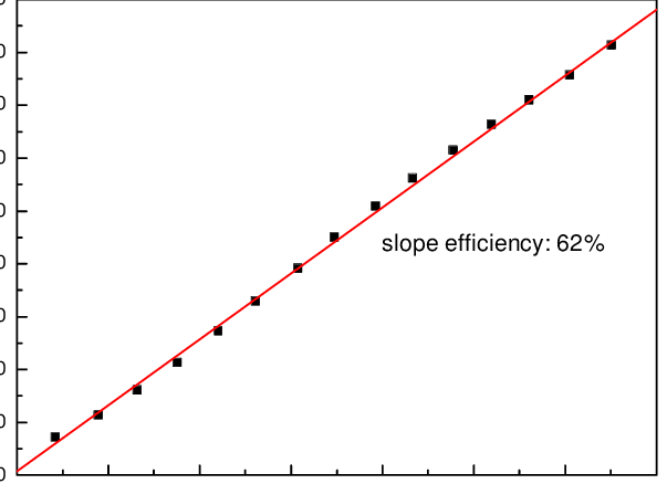 A 3000K blackbody emitter releases 6% of its energy in that band. At 20 kg/m^2, this gives a power density of 13.8 kW/kg. We will cut off 10% due to losses involved in the filtering and internal optics.
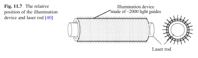 As before, the laser crystal itself handles enough pumping power on its own to have a negligible mass.The radiators operating at 789K will require carbon fiber panels. They’ll manage a power density of 22 kW/kg.Optimistically, we can expect a power density of 3.7 kW/kg (reduced by 15%) when we include all the components necessary.Ultra-high-temperature blackbody pumped laserWe must increase the temperature of the blackbody emitter. It can radiate more energy across the entire spectrum, and concentrates it in a narrower selection of shorter wavelengths.Solid blackbody surfaces are insufficient. To go beyond temperatures of 4000K, we must consider liquid, gaseous and even plasma blackbody emitters. This requires us to abandon conventional solid-fuel reactors and look at more extreme designs.There is a synergy to be gained though. The nuclear fuel can also act as blackbody emitter if light is allowed to escape the reactor.Let us consider two very high to ultra-high temperature reactor designs that can do that: a 4200K liquid uranium core with a gas-layer-protected transparent quartz window and a 19,000K gaseous uranium-fluoride ‘lightbulb’ reactor.For each design, we will try to find an appropriate laser that makes the best use of the blackbody spectrum that is available.4200K:
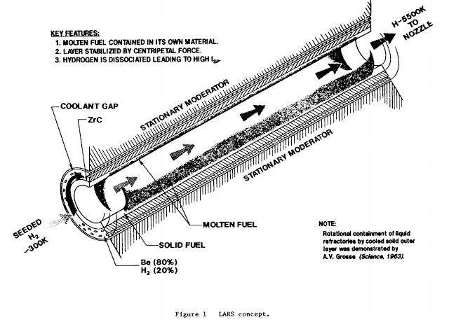 Uranium melts at 1450K and boils at 4500K. It can therefore be held as a dense liquid at 4200K. We base ourselves on this liquid-core nuclear thermal rocket, where a layer of fissile fuel is held against the walls of a drum by centrifugal effects. The walls are 10% reflective and 90% transparent.The reflective sections hold neutron moderators to maintain criticality. This will be beryllium protected by a protected silver mirror. It absorbs wavelengths shorter than 250 nm and reflects longer wavelengths with 98% reflectivity.
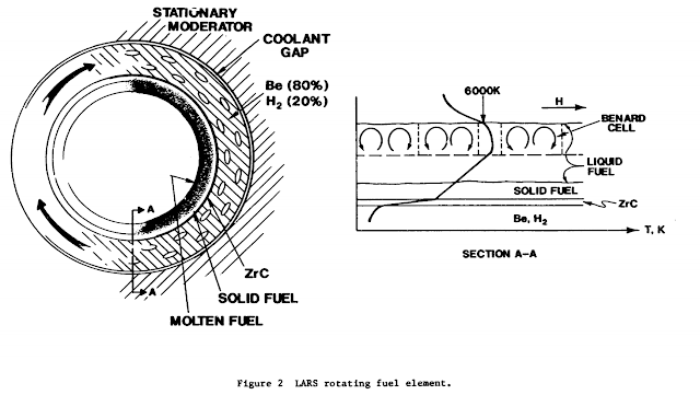 We expect the neutron moderator in the reflective sections, combined with a very highly enriched uranium fuel, to still manage criticality. The spinning liquid should spread the heat evenly and create a somewhat uniform 4200K surface acting as a blackbody emitter.
 The transparent sections are multi-layered fused quartz. It is very transparent to the wavelengths a 4200K blackbody emitter radiates – this means it does not heat up much by absorbing the light passing through.We cannot have the molten uranium touch the drum walls. We need a low thermal conductivity gas layer to separate the fuel from the walls and act like a cushion of air for the spinning fuel to sit on. Neon is perfect for this. It is mentioned as ideal for being placed between quartz walls and fission fuel in nuclear lightbulb reactor designs. The density difference between hot neon gas and uranium fuel is great enough to prevent mixing, and the low thermal conductivity (coupled with high gas velocity) reduces heat transfer through conduction. We might aim to have neon enter the core at 1000K and exit at 2000K.
 There is still some transfer of energy between the fuel and the walls because the mirrors are not perfect; about 1.8% of the reactor’s emitted light is absorbed as heat in the walls. Another 0.7% in the form of neutrons and gamma rays enters the moderator. We therefore require an active cooling solution to channel coolant through the beryllium and between the quartz layers. Helium can be used. It has the one of the highest heat capacities of all simple gases, is inert and is even more transparent than quartz.Beryllium and silver can survive 1000K temperatures, so that will set our helium gas temperature limit.A heat exchanger can transfer the heat the neon picks up to the cooler helium loop. The helium is first expanded through a turbine. It radiates its accumulated heat at 1000K. It is then compressed by a shaft driven by the turbine.If we assume that the reactor has power density levels similar to this liquid core rocket (1 MW/kg) and that 2.5% of its output becomes waste heat, then it can act as a blackbody emitter with a power density of 980 kW/kg. Getting rid of the waste heat requires 1 mm thick carbon fiber radiators operating at 1400K. Adding in the weight of those radiators and we get 676 kW/kg.
 A good fit might be a titanium-sapphire laser. It would absorb the large range of wavelengths between 400 and 650 nm.
 That’s 18.5% of a 4200K emitter’s spectrum. If we use a diffraction grating to filter out just those wavelengths, and include some losses due to internal optics, we get 125 kW of useful wavelengths per kg of reactor-emitter.The crystal can operate at up to 450K temperature, with 40% efficiency. Other experimentsinto the temperature sensitivity of the Ti:Al2O3 crystal reveals lasing action even at 500K, with mention of a 10% reduction to efficiency. We will use the 36% figure for the laser to be on the safe side. Based on data from this flashpumping experiment and this crystal database, we know that it can easily handle 1.88 MW/kg. The mass contribution of the laser itself is negligible.Any wavelengths that get absorbed but are not turned into laser light become waste heat. At 450K temperature, we can still use the lower density by HDPE plastic panels to get a waste heat management solution with 4.6 kW/kg.Putting all the components together and applying a 15% penalty just to be conservative, we obtain an overall power density of 2.2 kW/kg.19,000:
 If we want to go hotter, we have to go for fissioning gases. Gas-core ‘lightbulb’ nuclear reactors will be our model.
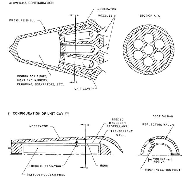 The closed-cycle ‘lightbulb’ design has uranium heat up to the point where it is a very high temperature gas. That gas radiated most of its energy in the form of ultraviolet light. A rocket engine, as described in the ‘NASA reference’ designs, would have the ultraviolet be absorbed by small tungsten particles seeded within a hydrogen propellant flow. 4600 MW of power was released from an 8333K gas held by quartz tubes, with a total engine mass of 32 tons.
 We want to use the uranium gas as a light source. More specifically, we want to maximize the amount of energy released in wavelengths between 120 and 190 nm. 19,000K is required. It is within reach, as is shown here.
 Unlike a rocket engine, we cannot have a hydrogen propellant absorb waste heat and release it through a nozzle. The NASA reference was designed around reducing waste heat to remove the need for radiators, but we will need them. Compared to the reference design, we would have 27 times the output due to the higher temperatures, but then we have to add the mass of the extra radiators.
 About 15% of the reactor’s output is lost as waste heat in the original design. It was expected that all the remaining output is absorbed by the propellant. We will be having a lasing gas instead of propellant in between the quartz tube and the reactor walls. The gas is too thin to absorb all the radiation, so to prevent it all from being absorbed by the gas walls, we will use mirrors.Polished, UV-grade aluminium can handle the UV radiation. It reflects it back through the laser medium and into the quartz tubes to be recycled into heat. Just like the blackbody-pumped Nd:YAG laser, we can create a situation where the pumping light makes multiple passes through the lasing medium until the maximum fraction is absorbed.
 Based on this calculator and this UV enhanced coating, we can say that >95% of the wavelengths emitted by a 19,000K blackbody surface are reflected.In total, 20% of the reactor’s output becomes waste heat.Since aluminium melts at 933K, we will keep a safe temperature margin and operate at 800K. This should have only a marginal effect on the mirror’s reflective properties. Waste heat must be removed at this temperature. As in the liquid fuel reactor, the coolant fluid passes through a turbine, into a radiator and is compressed on its way back into the reactor. Neon is used for the quartz tube, helium for the reactor walls and the gaseous lasing medium is its own coolant.Based on the reference design, the reactor would have 4.56 MW/kg in output, or 3.65 MW/kg after inefficiencies. If the radiators operate at 750K and use carbon fiber fins, we can expect a power density for the reactor-emitter of 70.57 kW/kg.28.9% of the radiation emitted by a 19,000K blackbody surface, specifically wavelengths between 120 and 190nm, is absorbed by a Xenon-Fluoride gas laser.
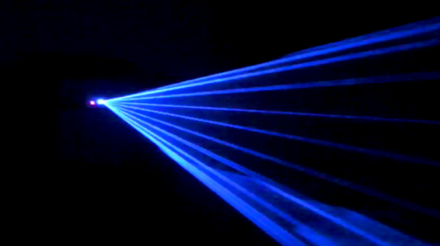 They are converted into a 350nm beam with 10% efficiency in a single-pass experiment. In our case, the lasing medium is optically thin. Much of the radiated energy passes through un-absorbed. The mirrors on the walls recycles those wavelengths for multiple passes, similar to the Nd:YAG design mentioned previously. Efficiency could rise as high as the maximal 43%. This paper suggests the maximal efficiency for converting between absorbed and emitted light is 39%. We’ll use an in-between figure of 30%. This means that the effective power density of the reactor-emitter-laser system is 6.12 kW/kg.
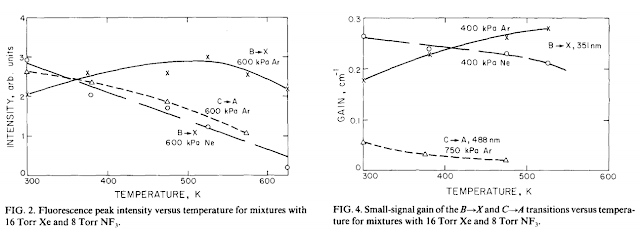 The XeF lasing medium is mostly unaffected by temperatures of 800K, so long as the proper density is maintained. We can therefore cool down the lasing medium with same radiators as for the reactor-emitter (17.94 kW/kg). When we include the waste heat of the laser, we get an overall power density of 2.9 kW/kg, after applying a 15% penalty.A better power density can be obtained by having a separate radiator for each component that absorbs waste heat (quartz tubes, lasing medium, reactor walls) so that they operate at higher temperatures, but that would be much more complex.Aerosol fluorescer reactorThe design can be found with all its details in this paper.
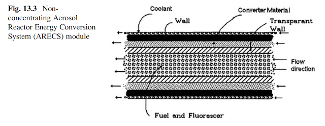 Tiny micrometer-sized particles of fissile fuel are surrounded in moderator and held at high temperatures. Their nuclear output, in the form of fission fragments, escapes the micro-particles and strikes Xenon-Fluoride or Iodine gas mixtures to create XeF* or I2* excimers. These return to their stable state by releasing photons of a specific wavelength through fluorescence. Their efficiency according to the following table is 19-50%.
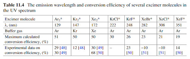 Simply, it is an excimer laser that is pumped by fission fragments instead of electron beams. I2* is preferred for its greater efficiency and ability to produce 342 nm beams. Technically, this is an indirect pumping method, but it shares most of its attributes with direct pumping reactor lasers.
 The overall design is conservatively estimated at 15 tons overall mass, but with improvements to the micro-particle composition (such as using plutonium or a reflective coating), it could be reduced even further. It is able to produce 1 MJ pulses of 1 millisecond duration. With one pulse a second, this a power density of 66 W/kg. One hundred pulses mean 6.6 kW/kg. One thousand pulses, or quasi-continuous operation, would yield 66 kW per kg.
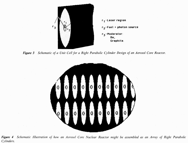 The only limit to the reactor-laser’s power density is heat build-up. At 5% efficiency, there is nineteen times more waste heat than laser power leaving the reactor. We expect that using the UV mirrors from the previous design could drastically improve this figure by recycling light that was not absorbed by the lasing medium in the first pass through. Thankfully, the 1000K temperature allows for some pretty effective management of waste heat.Carbon fiber panels of 1mm thickness, operating at 1000K would handle 56.7 kW/kg. It would give the reactor a maximum power density of 2.4 kW/kg, including a 15% penalty for other equipment.If the reactor can operate closer to the melting point of its beryllium moderator, perhaps 1400K, then it can increase its power density to 8.3 kW/kg.ConclusionReactor lasers, when designed appropriately, allow for high powered lasers from lightweight devices. We have multiple examples of designs, either from references or calculated, that output several kW of laser power per kg.The primary limitations of many of the designs can be adjusted in ways that drastically improve performance. The assumptions made (for instance, 1 cm thick carbon emitter or flat panel radiators) are solely for the sake of easy comparison. It is entirely acceptable to use 1mm thick emitting surfaces or one of the alternate heat radiator designs mentioned in this previous blog post. Even better, many of the lower temperature lasers can have their waste heat raised to a higher temperature using a heat pump. Smaller and lighter radiators can then be used for a small penalty in overall efficiency to power the heat pumps.Most of the lasers discussed have rather long wavelengths. This is not great for use in space, as the distances they beam has to traverse are huge and it multiplies the size of the focusing optics required. For this reason, a method of shortening the wavelengths, perhaps using frequency doubling, is recommended. Halving the wavelength doubles the effective range. However, there is a 20-30% efficiency penalty for using frequency doubling. Conversely, lasers which produce short wavelength beams have a great advantage.The list of laser options for each type of pumping is also by no means exhaustive. There might be options not considered here that would allow for much greater performance… but research on such options is very limited. For example, blackbody and LED pumping seems to be a ‘dead’ field of research, now that diodes can produce a single wavelength of the desired power. Up-to-date performance of those options is therefore non-existent and so we cannot fairly compare their performance to lasers which have been developed in their stead.It should be pointed out that a direct comparison between reactor and electric lasers is not the whole story. Reactor lasers can easily be converted into dual-mode use, where 100% of their heat is used for propulsion purposes. A spaceship with an electric laser can only a fraction of their output in an electric rocket. For example, the 4200K laser can have a performance close to the liquid-core rocket design it was derived from. Other, like the aerosol fluorescer laser, can both create a beam and heat propellant at the same time. A nuclear-electric system must choose where to send its electrical output and must accept the 60% reduction in overall power due to the conversion steps between heat and electricity at all times.Finally, certain reactor lasers have hidden strength when facing hostile forces.Mirrors work both ways. The same optics and mirrors that transport your laser beam from the lasing medium out into space and to an enemy target can be exploited by an enemy to get their beam to travel down the optics and mirrors and reach your lasing medium.The lasing medium, assumed to be diodes or other semiconductor lasers, has to operate at relatively low temperatures and so it will melt and be destroyed under the focused glare of the enemy beam.Tactics around using lasers and counter-lasers, something called ‘eyeball-frying contests’ can sometimes lead to a large and powerful warship being brought to a stalemate by a small counter-laser.A nuclear reactor laser’s lasing medium can be hot gas or fissioning fuel. They are pretty much immune to the extra heat from an enemy beam. It would render them much more resistant to ‘eye-frying’ tactics.This, and many other strengths and consequences, become available to you if you include nuclear reactor lasers in your science fiction.
PS: I must apologize for using many sources that can only be fully accessed through a paywall. It was a necessity when researching this topic, on which little detail is available to the public. For this same reason, illustrations had to be derived from documents I cannot directly link to, but they are all referenced in links in this post. -
This is turning out to be really good. Supercruising already! Maybe try attacking some payloads to that plane? Also, how did you collect and display telemetry from the TV-2 launch?
-
16 hours ago, wumpus said:
I remember particle beams (particularly neutron beams: strip the protons off deuterium or similar means) being an important part of the SDI (Reagan's "Star Wars") program. Presumably because of accuracy, but I don't the lasers back then were anything like 21st century spec.
I'm a bit more curious if these would make insterstellar (ultra-high Isp) engines. Or at least somewhat more efficient than using a bunch of LEDs (essentially infinte Isp, but the worst energy efficiency out there) as thrusters.
To produce a very high Isp engine, you can use simple particle beams and adjust the beam velocity to match your Isp and thrust requirements. There is no need to keep the beam focused after it exits your spaceship, so a Laser-Coupled Particle Beam is of no use here.
-
15 hours ago, Cunjo Carl said:
I think I'll be reading through this one for a while. I like what you've got, and thanks for all the pretty pictures!
I think this is very key. Otherwise you need to make sure the battle's in a dusty nebulae or something for it to look as cool as it should. Plus, ion beams are more expensive, so they must be cooler
Interestingly, we actually do have normal incidence Xray mirrors. They're.... expensive. People use them for 'XUV' and 'EUV' nanolithography, where ridiculously high energy (low wavelength) light is used to pattern a surface at the nanometer scale typically to make transistors. I'm fortunate to have nothing to do with it! If you ask someone in nanotechnology about 'EUV' you're guaranteed to get a deep sigh and a grimace out of them. Holdups in EUV optics (largely the light sources at this point) are what's holding up moore's law at the moment. Still, they got the mirrors going! Just for an example, here's an outfit that will sell you a 50cm Xray mirror, probably for the price of a modest house: http://www.ntt-at.com/product/multilayer/
It might be interesting to consider very high energy ion beams (.9999___9999 c). Despite their mutual repulsion, when ions go fast enough they become very heavy (from relativity) which prevents them from diverging atleast quite as much as we'd expect, especially for ranges in the 100,000km ballpark. An example would be the LHC with it's (checks wiki) 6.5TeV protons which are 7000 times heavier than a normal proton, and future technologies should increase this dramatically further. (The main thing preventing a ring from accelerating ions even faster is that synchrotron radiation with higher speed ions in ring accelerators starts to warm up the cryogenic superconducting rings. There are engineering solutions to this however, which may be available in the future. These can also make rings smaller.) You can also accelerate heavy ions like gold to further increase mass per charge without increasing ring size.
One further nice effect of very high energy ions is the wonderful terminal ballistics! They have a nice bonus effect where the ions will actually penetrate deep into materials before depositing their energy and causing damage. The depth they penetrate is called their Bragg peak, and it can be extremely deep and consistent with cold ion beams. A present day constructive use of this property is proton therapy, which is commonly used to treat inoperable eye tumors. You literally stare into a particle accelerator, and if fires protons into your eye which don't interact until just the depth the tumor's at where they do the damage to destroy it. I've also seen it used to slice sheets off of a surface (in Silicon) by rastering the ion beam and destroying the material beneath the surface over a large area. Bragg peaks start to disappear for GeV protons, but I read once they reappear at higher energies? I'd need to look into it. Anyways: https://www.bnl.gov/nsrl/userguide/bragg-curves-and-peaks.php
Ah, here's the Bragg peak for TeV protons. Looks like it reappears at ~20cm penetrations for 50TeV protons in copper: https://journals.aps.org/prab/pdf/10.1103/PhysRevAccelBeams.20.081001
That'd be pretty cool, right? Carving off 20cm chunks of armor! That's definitely something the lasers won't do.
I point you to the previous ToughSF post: http://toughsf.blogspot.com/2018/12/particle-beams-in-space.html
It covers many of the points you just mentioned.
-
Hi all! This is from: http://toughsf.blogspot.com/2019/02/cold-laser-coupled-particle-beams.html
This is a follow-up to the Particle Beams in Space post.
This time, we look at two concepts that can massively increase the effective range of particle beam: one is being applied every day in modern accelerators, and the other is an outgrowth of a tool used in biophysics.Everything here is based on science that has been worked upon by physicists and engineers, and will be referenced when possible.
Performance limits
The key characteristics of a particle beam are its divergence, particle energy and average power. Improving these characteristics leads to increases in overall performance. However, we know that there are limits to the performance that is possible.
One limit is the ion source. The emittance of current ion sources are where they are at today due to the need to vaporize the ions into a gas (which imposes a minimum temperature) and the interactions between ions and energetic electrons or strong magnetic fields (which disturbs the ions).
Expanding the beam to convert emittance into low divergence introduces its own errors and disturbances.
Another limit is the neutralization step. Even when an ion beam and an electron beam are exactly matched in velocity and direction, their recombination into an atom releases energy that kicks particles in random directions. The magnitude of the kick cannot be reduced by any means, so there is a minimum divergence in neutral beams.
Optimizing the beam composition to reduce emittance introduces other problems. The elements that vaporize at a low temperature and have a low ionization energy for their weight (like Cesium) are always heavy. For the same energy added to them, they end up travelling much slower than light elements. For example, 250 MeV added to Cesium only pushes it to travel at 0.063 C while hydrogen atoms of the same energy zip past at 0.613 C. This increases the travel time necessary to reach a target, leading to greater beam spread and a lower hit chance.
Finally, there are the accelerator limitations. For a specific emittance, you can reduce divergence linearly by expanding the beam or speeding it up. Beam expansion becomes more and more difficult in terms of magnetic lens field strength requirements as the beam energy and current increases. Speeding up the beam requires quadratic length increases for each small gain in velocity. Attaining the desired level of performance might lead to gargantuan accelerators.
Beating the laser
The limitations of particle beams are particularly relevant when comparing them to lasers. Both are directed energy technologies that try to cross great distances while maintaining a small beam diameter. A fair comparison between the two would use emittance and divergence.
The neutral particle beams that we can produce today are equivalent in emittance to laser beams with wavelengths of about 100 to 200 nanometers. Lasers struggle to produce these wavelengths efficiently and so particle beams should have the upper hand. However, lasers can work around their emittance by using large mirrors. Just like a particle beam expander, laser optics allow for very low divergence even when using longer wavelengths, such as 700 to 800 nanometers.
Cooled diode lasers are achieving efficiencies of over 80% when producing those wavelengths, eliminating that advantage from a particle beam.
In essence, lasers can trade the complex and heavy equipment needed to beat particle beams on an emittance basis, for the simple and lightweight solution that is large mirrors.Even better, mirrors can relay the beam over great distances with minimal losses, resulting in a Laser Weapon Web.
The cutting edge of existing technology, paired with beam expanding optics and the use of heavy ions, could produce neutral particle beams with a divergence of 1 to 10 nanoradians. Equivalent laser beams of 1 to 10 nanometers can only be produced by an X-ray Free Electron Laser (XFEL). Comparing between advanced particle beams and XFELs is more nuanced.
XFELs use the same accelerator technology to create a high energy stream of electrons. The electrons can be recycled many times and their energy recovered, leading to efficiencies perhaps greater than particle beam accelerators. At the ranges where an advanced particle beam and an XFEL are effective, light lag is significant. Lasers win out here again as they are many times faster than heavy neutral beams.
However, XFELs have their own unique challenges. They need an undulator to convert the energy of their electrons into photons. It can only extract 0.1% of the electron energy with each pass. Recently, we have devised solutions, such as tapered undulators, that extract up to 10% of the electron energy. This is far below the 100% utilization of a particle beam, so while they may have a 10 to 20% advantage in efficiency, they could end up with a 10 to 100 fold penalty to power density. In other words, for the same mass budget, a spaceship is likely to output much less beam power when using an XFEL than when compared to using a particle beam.
X-rays are very hard to manipulate. There exists no mirror that can reflect them and no lens which can focus them.
An XFEL would have to rely on grazing-incidence optics to aim and focus its beam. Grazing-incidence optics are nestled cones of a dense metal like gold angled at 1 degree or less.
Such an optic would need many, many such cones even at small sizes. As the focal distance increases, the angle of the cones must decrease. A 1 meter diameter optic focused at a spot 10,000km away requires cones of an angle 2.86 *10^-6 degrees. This leads to optics composed of no less than millions of cones, which is incredibly impractical and necessarily heavy. It should also be noted that grazing incidence optics cannot adjust their focal point.
The alternative is a Fresnel Zone plate. It is not as delicate or as intricate as a grazing incidence optic, can adjust its focus and can be a rather lightweight device even when several meters wide. The ‘catch’ is that it absorbs between 50 and 75% of the laser beam.
The plate also needs to be actively cooled and reduces the efficiency of an XFEL far below that of a particle beam accelerator.Does this mean particle beams are safe? Not yet!
XFELs might regain the upper hand by using new methods of focusing X-rays.
Bent diffraction crystals can reach high diffraction efficiency, which would make them very good at focusing X-rays. There could be further development of highly efficient Kinoform lenses.
Alternatively, XFELs enjoying improvements in accelerator technology and undulator field strength can produce extremely short wavelengths, lower than 0.0001 nanometers, without requiring structures of several hundreds of meters in length. No focusing optics are needed in this case! Even a millimeter wide opening from an undulator is enough to produce beams of 0.3 nanoradian divergence. This performance is no more than 10x what is achievable today.We could therefore expect XFELs to end up creating 60 cm spot sizes at million kilometre distances. Their only limitation would be light lag. Can particle beams be competitive with such lasers?
Cold Ions
The most effective way to reduce the divergence of a particle beam down to its neutralization-imposed minimum is to reduce the emittance of the ion source.
The ions released from an ion source usually have a ‘temperature’ of about 1 eV. We have assumed so far that the particle accelerator uses the ions at this temperature and does not significantly increase or decrease it. This does not have to be the case.
Ions can be cooled after exiting their source and before they are accelerated to higher energies. Beam cooling techniques that can be used here include stochastic, radiative and electron cooling.
Stochastic cooling inside a low-energy ring uses electromagnets to try to correct the path of a beam so that all the particles have a very similar temperature instead of a range of temperatures.
Radiative cooling only works practically with electron beams. It forces the electrons to wiggle to maximize their energy loss through Bremsstrahlung radiation. Energy is then added back to the electrons only in the longitudinal direction, leading to a gradual reduction in transverse temperature.
Electron cooling involves mixing hot ions with cold electrons (themselves cooled radiatively) to reduce the ion temperature. After mixing, the beam is bent by electromagnets so that the ions and electrons separate into different paths.
All these techniques require multiple passes to be truly effective and therefore work best in a ring-shaped accelerator. Low energy ions produced by an ion source are easily bent into a circle by lightweight magnets. Over the course of several seconds or even minutes, ions are run around and around the the ring and passed multiple times through a cooling section. Eventually, the ion temperature approaches that of the electrons.
Regular electrons will have the temperature of their emitter, 2000 to 3000 K, which corresponds to 0.17 to 0.26 eV. A photocathode emitter, where laser light is used to expel electrons from a surface, can produce electrons as cool as 1.5 meV or 17.4 K. They will be further cooled down to the tens of kelvins.
If such low electron temperatures are accessible, and a ring accelerator can be used to bring ions down to similar temperatures, then there is the possibility of of creating cryogenic ion beams. They would have a near-zero emittance if it were not for electrostatic repulsion and internal collisions between the charged particles.Cryogenic particle beams are the solution to obtaining divergence no greater than the minimum imposed by neutralization disturbance, and this does not involve any expanding or focusing optics.
There is a secondary advantage to cryogenic particle beams that can allow them to reach divergence even lower than the neutralization minimum.
A bunch of neutral atoms travelling through space in a dense stream is not really different than a quick-moving gas. Cold gases condense.
Cold hydrogen atoms condense into H2 droplets. Nitrogen condenses into N2. Cesium atoms condense into solid metal balls. The higher the vaporization temperature (hydrogen boils at 10 K in vacuum, but nitrogen only needs to be cooler than 63 K), the more likely that the particle beam condenses into a stream of higher molar mass entities.
When two atoms join into a molecule, they average their transverse velocities. This effectively reduces the divergence of a particle beam by 42%.
The square root of the mass ratio between the final condensed product and the individual atoms gives the reduction in divergence. This phenomenon was critical to Geoffrey A. Landis’s ‘Interstellar Flight by Particle Beam’ paper, where he suggested that mercury atoms would condense into million-particle droplets.With ion cooling and condensation, we can obtain the sub-nanoradian particle beams necessary to compete with future XFEL performance.
Going further, we could expect beams of multiple species. Carbon and hydrogen beam are especially interesting. Carbon atoms at 1000 MeV could be released in parallel with hydrogen atoms at 80.3 MeV. Some of the hydrogen condenses into H2 and eventually diverges away, but they only carry a fraction of the energy. Carbon and hydrogen could instead condense into methane. The divergence of the carbon beam would be reduced by a 13.4%, and that of the hydrogen beam by 50%. When the methane molecules strike a target surface, they separate back into carbon and hydrogen. The carbon would stop very quickly and deposit all of its energy near the surface. The hydrogen is much more penetrating and would continue deeper into the material.
A methane beam would deliver both thermal and radiation damage and help defeat protection optimized for one or the other, all while maintaining a divergence much smaller than a pure radiation beam. Even better, the carbon would help ‘carry’ penetrating hydrogen particles through magnetic fields that would otherwise deflect lightweight hydrogen on its own. Methane is after all just 8% easier to ionize than hydrogen but 16 times harder to deflect.
Laser Coupled Particle BeamsThere is another method of reducing emittance which is radically different from those mentioned so far. It is based on optical tweezers that are known for trapping and manipulating tiny particles using laser beams.
The same method can be used to control the motion of particles in a particle beam. It is studied as part of NASA’s Innovative Advanced Concepts, promising diffractionless beams across interstellar distances. We will call them ‘Laser-Couple Particle Beams’ or LCPBs.
Can be applied in the context of distances on the order of 1,000 to 1,000,000 kilometers?
A laser beam can be used to create a column of light pointed at a target. The intensity of the laser varies from the edge to the center of the column in a gaussian profile. To simplify, we can say that the laser at the center of the column is twice as intense as the average intensity.
When a particle beam is inserted into the column and travels parallel to it, it experiences a force pushing its particles towards the center of the column. That is the gradient force.
We are solely interested in particles sitting at the edge of the column, as they determine the divergence. They experience the full pull of the gradient force.
As best that can be determined, the maximal acceleration towards the center of the laser column that a particle experiences is as follows:- Average Particle Acceleration = (0.5 * AP * IG * DRF)/PM
AP is the atomic polarizability.
IG is the intensity gradient of the laser, in W/m^2/m
AAG is the average acceleration factor, drawn from the table below.
PM is the particle mass in kg.
The AAG is the result of the particles experiencing less and less gradient force drawing them towards the center of the laser column as they come closer. It is the result of the intensity gradient falling as they do so. The greater the reduction in divergence we want, the lower the average acceleration the particles experience.
From the table, we can read that if we want to reduce the divergence by a factor 8, the average acceleration the particles experience is 34% of the initial acceleration.AP values can be found here (https://cccbdb.nist.gov/pollistx.asp) in multiples of the radius cubed.Hydrogen, with a radius of 5.29 * 10^-11 m, would have a polarizability of 0.667 * (2.5 * 10^-11)^3: 1.04*10^-32.
Potassium, with a radius of 2.2*10^-10 m, would have a polarizability of 43 * (2.2*10^-10)^3: 4.58*10^-28.
IG for a gaussian beam is roughly twice the average laser intensity (W/m^2) divided by the laser beam’s radius.
Using three worked examples, we can clearly see that LCPBs can have massively extended ranges when compared to either lasers or particle beams alone. We assume that they have received the beam cooling treatment and that their initial divergence is roughly equal to the minimum imposed by neutralization.
In the first example, we will calculate the laser parameters needed to reduce the divergence of a 1 meter wide, 100 MeV hydrogen beam from 54 nanoradians to 5.4 nanoradians within a distance of 1,000 km.
Hydrogen at 100 MeV is travelling at 0.428 C or 128,360 km/s, so it crosses a distance of 1,000 km in about 7.79 milliseconds. An initial divergence of 54 nanoradians implies that it spreads at a rate of 6.93 m/s. We therefore need to reduce the transverse velocity from 6.93 m/s to 0.69 m/s within 7.79 milliseconds. That is an acceleration of 801 m/s^2.
We’re trying to reduce the divergence by a factor 10, so the average acceleration is 29.3% of the initial acceleration. Conversely, the initial acceleration will have to be 3.41 times greater to achieve the desired average acceleration, about 2732 m/s^2.
We input PA = 2732 m/s^2, AP = 1.04*10^-32 and PM = 1.67*10^-27 kg. From that, we determine that IG = 8.8*10^8 W/m^2/m
Since the beam is 1 meter in diameter, it has a radius of 0.5 meters, so average laser intensity will be 219.4 MW/m^2. This is not unreasonable. The total laser power required is 172.3 MW. It is quite a big penalty to the power requirements of the particle beam.
In the second example, we will calculate the laser parameters needed to reduce the divergence of a 1 meter wide, 300 MeV Xenon beam from 2.5 nanoradians to 0.25 nanoradians within a distance of 1,000 km.
Xenon at 300 MeV is travelling at 0.0697 C or 20,890 km/s, so it crosses a distance of 1,000 km in about 47.87 milliseconds. An initial divergence of 2.5 nanoradians implies that it spreads at a rate of 0.05 m/s. We therefore need to reduce the transverse velocity from 0.05 m/s to 0.005 m/s within 47.87 milliseconds. That is an acceleration of 0.982 m/s^2.
The divergence reduction factor is 10, so the average acceleration is
29.3% of the initial acceleration. We therefore need an initial acceleration of 3.34 m/s^2.
We input PA = 3.34 m/s^2, AP = 5.04*10^-30 and PM = 2.18*10^-25 kg. From that, we determine that IG = 2.89*10^5 W/m^2/m
The average laser intensity will be 72.4 kW/m^2 and total laser power is just 56.7 kW! This is a very minor penalty to a particle beam accelerator with a several megawatt output.
In the final example, let’s try for a very narrow beam, using condensation to produce a molecule with very low initial divergence and high polarizability. Lets’ also be generous with the particle energy.
Starting with 1000 MeV Cesium (min divergence 0.43 nrad) and 955 MeV Iodine (min divergence 1 nrad), we expect to end up with Cesium Iodide with a polarizability of 1.94*10^-28, based on an average of the two element’s Van der Wall’s radii figures fromhere. The divergence of the molecule is 0.7 nrad and it will be travelling at 0.126 C or 37,800 km/s.
What laser is needed to reduce the divergence of a 1 millimeter wide, Cesium-Iodine beam from 0.7 nanoradians to 0.035 nanoradians within a distance of 1,000 km?
The 0.126 C beam crosses a distance of 1,000 km in about 26.45 milliseconds. An initial divergence of 0.7 nanoradians implies that it spreads at a rate of 0.021 m/s. We therefore need to reduce the transverse velocity from 0.021 m/s to 0.00108 m/s within 26.45 milliseconds. That is an acceleration of 0.776 m/s^2.
The divergence reduction factor is 20, so the average acceleration is
18% of the initial acceleration. We therefore need an initial acceleration of 4.3 m/s^2.
We input PA = 4.3 m/s^2, AP = 1.94*10^-28 and PM = 4.32*10^-25 kg. From that, we determine that IG = 1.92*10^4 W/m^2/m
The average laser intensity will be 4.78 W/m^2 so total laser power is a rather incredible 0.37 … milliWatts.
Summary of results:
Example 1
Particle: 100 MeV Hydrogen
Initial divergence: 54 nrad
Final divergence: 5.4 nrad
Power required: 172.3 MWExample 2
Particle: 300 MeV Xenon
Initial divergence: 2.5 nrad
Final divergence: 0.25 nrad
Power required: 56.7 kWExample 3
Particle: 1000 MeV Cesium and 955 MeV Iodine
Initial divergence: 0.7 nrad
Final divergence: 0.035 nrad
Power required: 0.37 mW
These are the theoretical minimum values, assuming maximal optical tweezer gradient force and that 100% of the laser energy goes towards pushing particles together. However, if even a fraction of this performance is attainable (you can always compensate with stronger lasers, rising from milliwatts to watts), then particle beams with a tenth of a nanoradian in divergence are attainable.
In the final example, we find that LCPBs are able to act like ‘pencil beams’ that barely spread from the moment they exit their millimeter-sized ports to when they produce spot sizes on the order of 3.5 cm at 1 million km.
Fighting with LCPBs
It should be evident by now that if we start off with a beam of low divergence and narrow diameter, we can use very moderate laser power to significantly reduce divergence. LCPB ‘pencil beams’ would be able to produce small spot sizes at extreme distances. They would dominate the field of directed energy weapons and would be the ideal power transmission tool for interplanetary or interstellar propulsion. A 0.1 nanoradian divergence beam would concentrate its energy within a 0.03 m^2 spot at a million kilometers, or catch a 100 meter wide receiver from a distance of 500 million km. The latter is 33% more than the distance from the Earth to Mars… if they were on opposite sides of the Sun!
LCPBs will dominate only within distances that they can reliably hit a target though. Their main limitation would be their velocity. The beam velocity does not matter when aiming at something that does not move appreciably in the time it takes the beam to reach it, or has a well defined trajectory, like an asteroid or a space station. LCPBs suffer instead when aiming at randomly maneuvering targets. The same random ‘jinking’ used to avoid lasers at distances where light lag is significant can be used at shorter ranges against the slower particle beams.Let’s take an enemy warship with a hull 10 meters wide. It can accelerate sideways at 1m/s^2.
If the beam travels at 0.07 C, like in the second example, then it will only hit that warship with 100% certainty out to a distance of 66,000 km. Accepting a hit rate of 50% only increases the distance to 77,000 km. It is a great distance, but only a tiny fraction of what the LCPB is capable of.
The enemy warship can reduce these ranges by accelerating harder. At 10m/s^2, the 100% hit distance is ‘just’ 21,000km. Of course, this consumes ten times more propellant.
A dumb but surefire way to defeat this enemy warship is to keep firing the LCPB until the jinking has consumed of its deltaV and renders it a non-maneuvering target. This might take minutes to days depending on the capabilities of the propulsion technology, and can be greatly extended by moving further away and reducing the acceleration. During this period, the enemy is firing back, a unenviable situation.
Smarter heads would choose to fire along a pattern that touches upon all potential positions the enemy warship can take. This way, a low hit chance can be converted into a low hit rate.
For example, a 0.07 C beam targeting a 10m wide target with 1 m/s^2 of acceleration would only have a hit chance of 1/82 at a distance of 200,000 km.
Instead of shooting spots at a random within the area of probable positions the target can take, the area is divided into sections, with each section given a fraction of the beam’s output. This way, instead of doing full damage with a 1.22% chance, we deal 1.22% damage all the time.
A 1000 MW LCPB with a 0.1 nanoradian divergence would have a spot size of 4 cm at 200,000 km. It should be able to burn through 24.6 m/s of graphite or 9.72 m/s of steel against an immobile target. Even after being divided and spread into 82 section to ensure a 100% hit chance, this is enough to maintain an average penetration rate of 30 cm/s against graphite and 11.8 cm/s against steel.Closing the distance greatly improves these numbers, as the beam becomes more intense and the target can take up less positions, so the beam power doesn’t have to be divided as much.
Performance table for a 1000 MW 0.1 nanoradian beam vs 10m target:
Base penetration rates
Target Material/Distance: Penetration rate
Graphite / 500,000 km: 0.843 m/s
Graphite / 250,000 km: 3.36 m/s
Graphite / 100,000 km: 20.8 m/s
Steel / 500,000 km: 1.76 m/s
Steel / 250,000 km: 6.46 m/s
Steel / 100,000 km: 32.9 m/s
Beam velocity: 0.01 C
Target acceleration/Distance/Sections: Average penetration rate vs graphite
1m/s^2 / 500,000km / 7,716,050: 0.11 micrometers/s
1m/s^2 / 250,000km / 482,250: 7 micrometers/s
1m/s^2 / 100,000km / 12,345: 1.7 millimeters/s
10m/s^2 / 250,000km / 48,225,300: 0.07 micrometers/s
10m/s^2 / 100,000km / 1,234,570: 16.8 micrometers/s
Beam velocity: 0.1 C
Target acceleration/Distance/Sections: Average penetration rate vs graphite
1m/s^2 / 500,000km / 771: 1.1 mm/s
1m/s^2 / 250,000km / 48: 70 mm/s
1m/s^2 / 100,000km / 1: 20.8 m/s
10m/s^2 / 250,000km / 4,822: 0.7 mm/s
10m/s^2 / 100,000km / 123: 169 mm/s
Beam velocity: 0.5 C
Target acceleration/Distance/Sections: Average penetration rate vs graphite
1m/s^2 / 500,000km / 1: 0.843 m/s
1m/s^2 / 250,000km / 1: 3.36 m/s
1m/s^2 / 100,000km / 1: 20.8 m/s
10m/s^2 / 250,000km / 8: 0.42 m/s
10m/s^2 / 100,000km / 1: 20.8 m/s
Based on these findings, LCPBs for combat would best be designed around produce a beam balanced between having enough speed to catch maneuvering targets and enough weight (molar mass) to maintain a low divergence.
Against large, relatively immobile targets like a space station or an asteroid fort, it is very easy to create very slow and very heavy beams that maintain an extremely low divergence across interplanetary distances.
Such ‘anti-fort’ beams would have penetration rates that could poke holes through hundreds of meters of rock and steel. The huge mass that serves as a great heatsink and helps ward off smaller warships using weapons of greater power and thus range in a laser vs laser scenario becomes a hindrance in an LCPB vs LCPB scenario.
The asteroid forts could try to retaliate with their own beams, but they will not be able to hurt maneuvering targets (look at how much average penetration drops as the number of sections increases) using LCPBs nor match their range using lasers.
Therefore, we can safely say that any large, mostly immobile structure can be defeated by a maneuvering LCPB-equipped spaceship.
The situation is more nuanced when it is a maneuvering spaceship against a Laser Weapon Web. LCPBs will lose if the LWW is able to bring their ‘terminal mirrors’ close to the LCPB to match its range faster than the LCPB or a radiation weapon can destroy them. This assumes the battles does not start with the LCPB-equipped spaceship already in range of a Laser Weapon Web, and if the power source of the LWW isn’t a planet protected by a thick atmosphere that particle beams cannot get through…
For SF authors and game designers, LCPBs have interesting tactical consequences.
The name of the game is balance.
The low-risk strategy in a one vs one situation is to spread the beam’s output and wait for the armor to be whittled away. A high-risk alternative is to drag the beam at random around the target and hope that when the beam does connect, it’s full-power penetration rate is enough to cut through the armor layer and get at the vital internal components. With computers and predictive software, a middle ground is likely to be sought instead: the target’s motions are predicted to lie along a certain path, and it is better to try to focus on getting a few good hits that get through the armor to start reducing the target’s ability to maneuver or fire back.Because of these tactics, it is suicidal to have no armor but also pointless to have too much armor. An unarmored craft can be destroyed by a sweep of a low powered beam while even a hundred meter boulder of graphite can be cut through end to end by a good hit from a LCPB.A balanced strategy with an optimum level of armor would deal damage the quickest and avoid harm the longest. Having massively more powerful beams, thicker armor or faster acceleration will not gain any decisive victory.
That is only passive armor though. We must include the threat from radiation beams and the option of active defenses.
Radiation beams would easily pass through the ‘optimal armor’ from an LCPB-balanced design. They require powerful magnetic fields to deflect instead. However, the power requirements and weight of equipment to surround a spaceship with a magnetic field sufficient to deflect the beam from an accelerator a fraction of the size and weight quickly becomes untenable. Instead of increasing the field strength to match the bending radius of more and more energetic particles, it is possible instead of physically move a smaller field outwards and into the beam path.
Smaller magnetic field generators can be fitted on drones and placed a kilometer or so away from the main spaceship. The ‘mag-shield’ drones only need to be strong enough to cause the incoming radiation to bend by an angle sufficient to miss the main spaceship.
For example, protecting a 10 meter wide spaceship using a mag-shield drone 1000 meters in front of it only requires that incoming beams be deflected by 0.29 degrees! This naturally allows for very small and weak fields to be used.
The downside to mag-shield drones is that they only work against beams coming from a small number of directions. An unexpected attack would be devastating. It wouldn’t have to be very powerful or intense to severely harm a living crew or sensitive electrons, as was demonstrated in the previous Particle Beam post. In fact, it could be the ideal weapon for deployment by cryogenic stealth craft, as they are the ones which could sneak into flanking attack vector and the low power requirements of a radiation weapon allows its waste heat to be entirely absorbed by the on-board cryogenic heatsink for minutes or even hours at a time.A second line of defense in the form of quick response mag-shield drones, that shoot out into the direction of an unexpected radiation beam, could be the difference between 0.1 seconds of sickening radiation and death.
What is the relationship between mag-shield drones and LCPBs?
The same concept can be used at even greater distances. The magnetic field will not be powerful enough to promptly ionize heavy particle beams approaching far below the speed of light, but it can work use its field to hold in a bubble of plasma. LCPB particles traversing a plasma can be quickly ionized, allowing them to be affected in turn by the magnetic field.
The further away the mag-shield drones are from the main ship, the weaker and lighter they can be, but also protect it from fewer directions.
Counter-beaming is another option. A LCPB’s arrival will be announced by a guide laser to give several seconds of warning at longer ranges. The targeted ship could aim down the beam path with its own laser. This ‘counter-LCPB’ beam would have an intensity profile opposite to that of a gaussian beam: weak in the center and intense at the edges. It would use the same Laser Coupling technique to push particles out of the center of the beam and therefore increase divergence.C-LCPBs will have a tough time as they have a narrow window of opportunity to get themselves aligned as well as possible with the incoming LCPB. They can never be perfectly parallel with the incoming beam, so they are less efficient. Worse, their need for large lenses makes them hard to protect when they become targets themselves.
From a visual perspective, battles involving LCPBs are more interesting than laser-dominated combat.
The neutralization step emits a small bit of light at the beginning of the particle beam's journey. Its guide laser will leave a dim trail of scattered photons from where it interacts with the particle beam. A brighter flash will occur where an ionizing laser meets an incoming LCPB, with the most spectacular sight being the interaction with a plasma bubble. C-LPBs have to make up for their reduced efficiency by using more power. This power ends up scattered as photons anyone can see.
This was prepared with the gracious help of GerritB, Kerr and Imallett. -
Yeah, it's very well done!
-
Thanks for taking the time to show those... mistakes!
Turbo-electric turboprops is an interesting choice. I would think that if fuel is the limiting factor, then fuel-electric-motor-prop is a less efficient use of it than simply fuel-motor-prop.

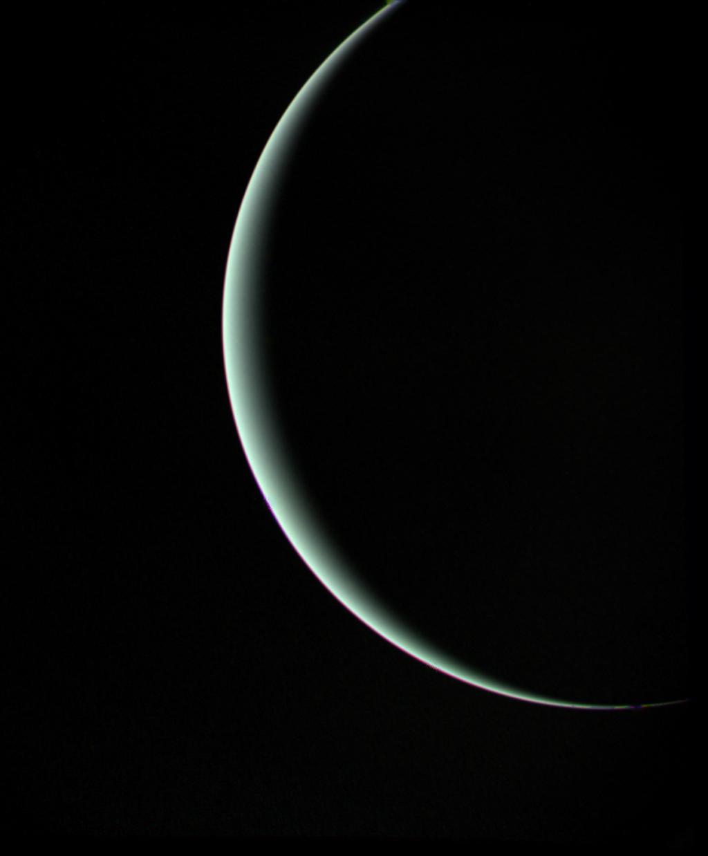


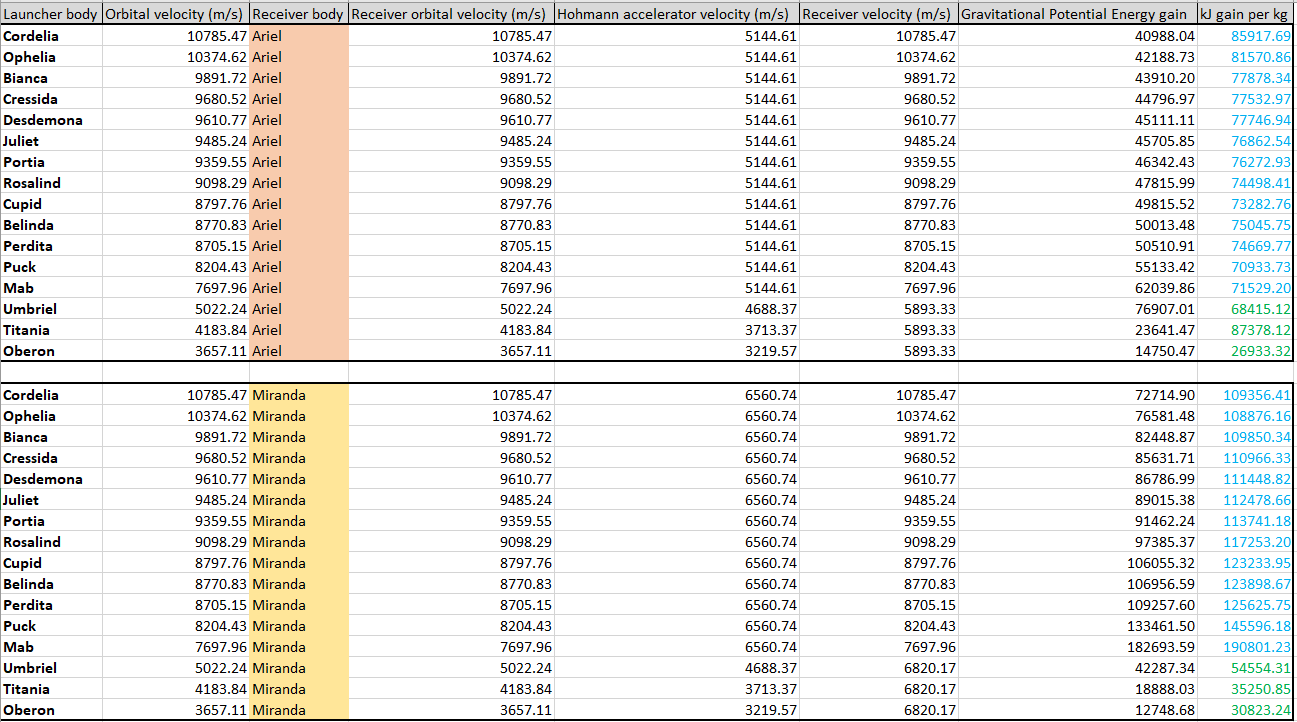


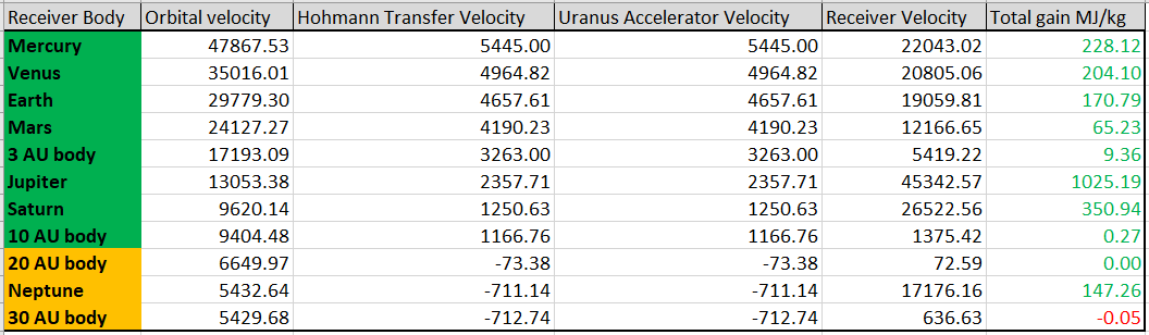
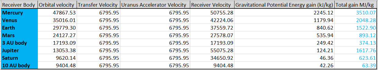


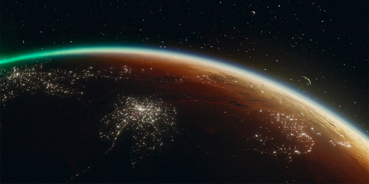
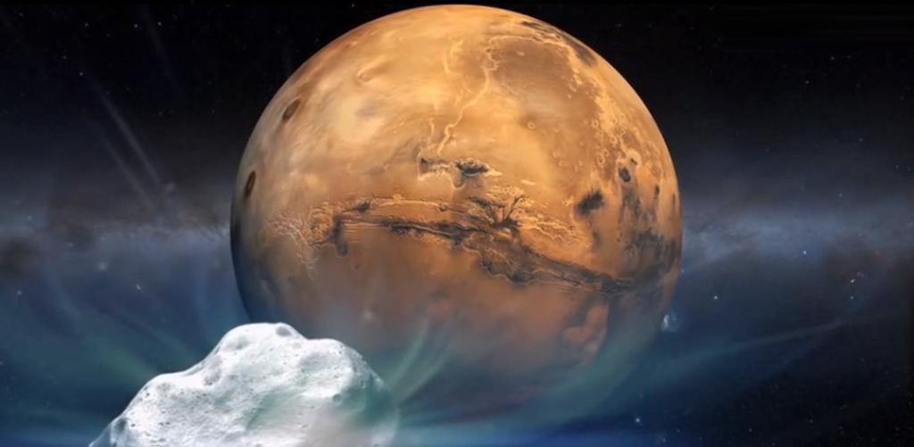


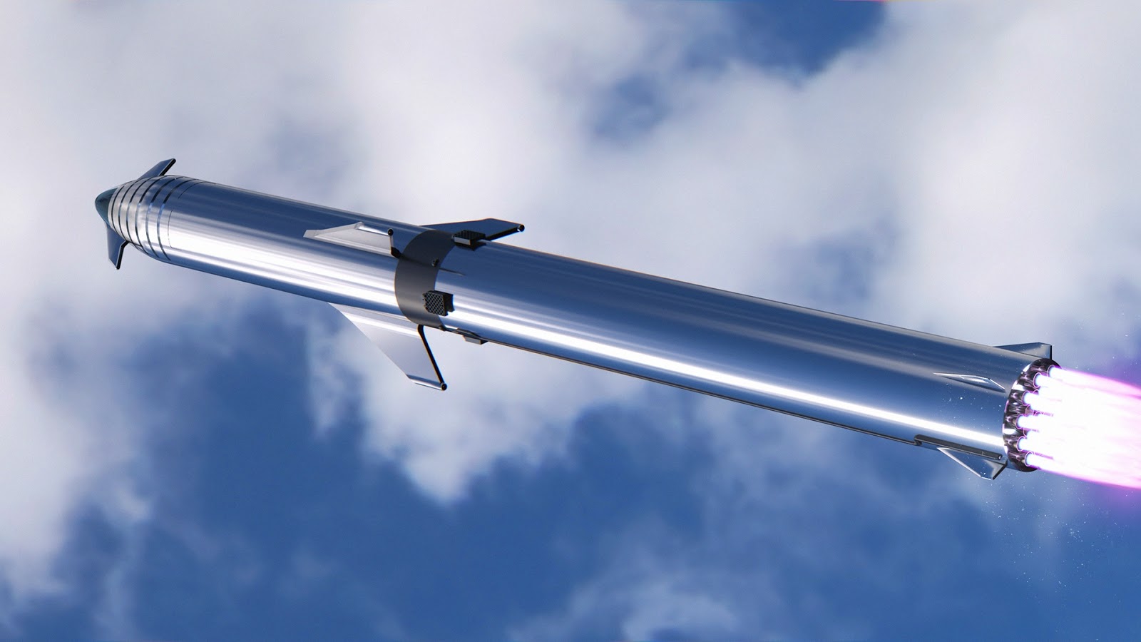


")


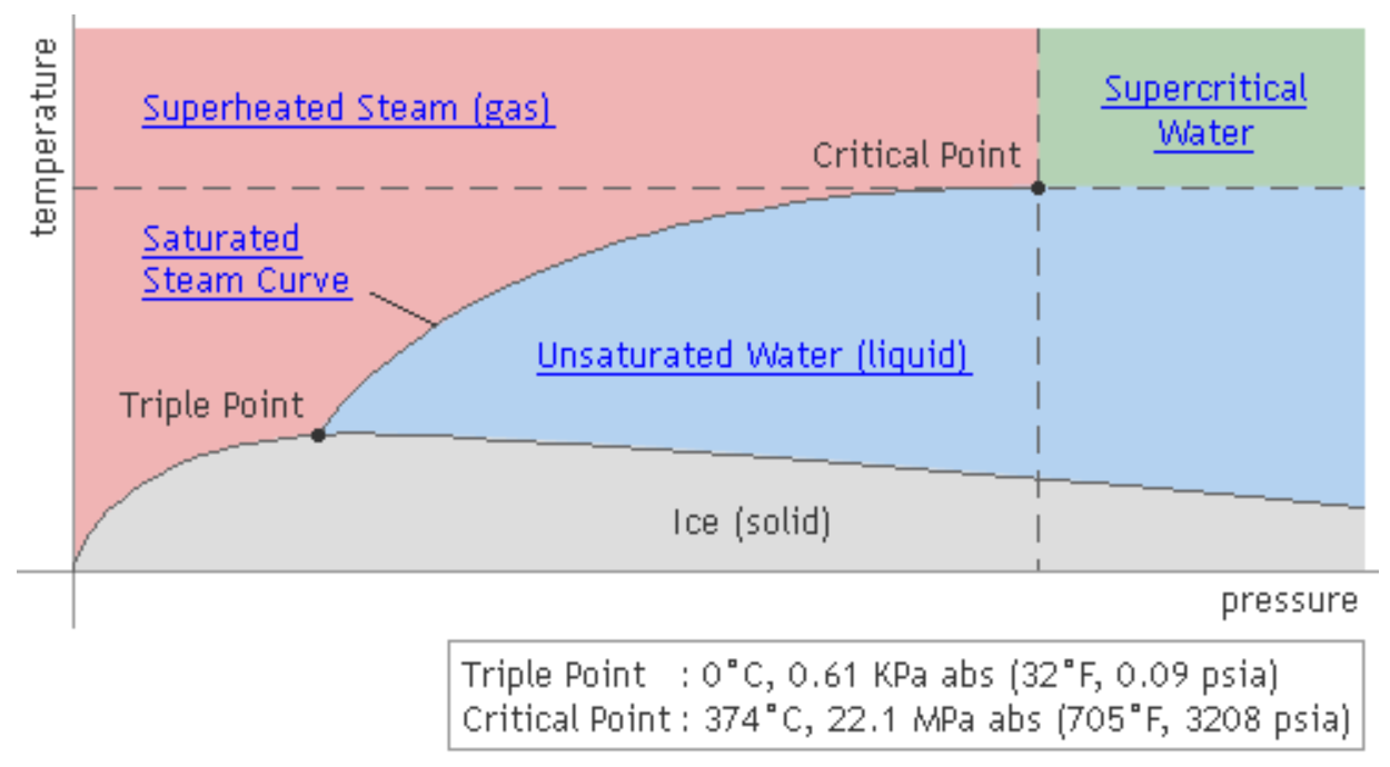


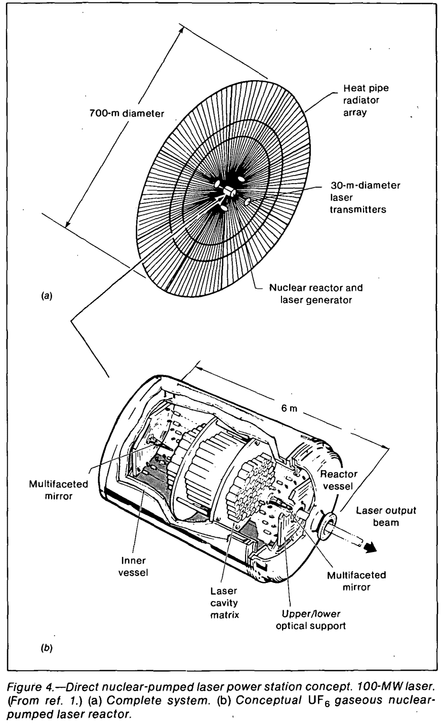
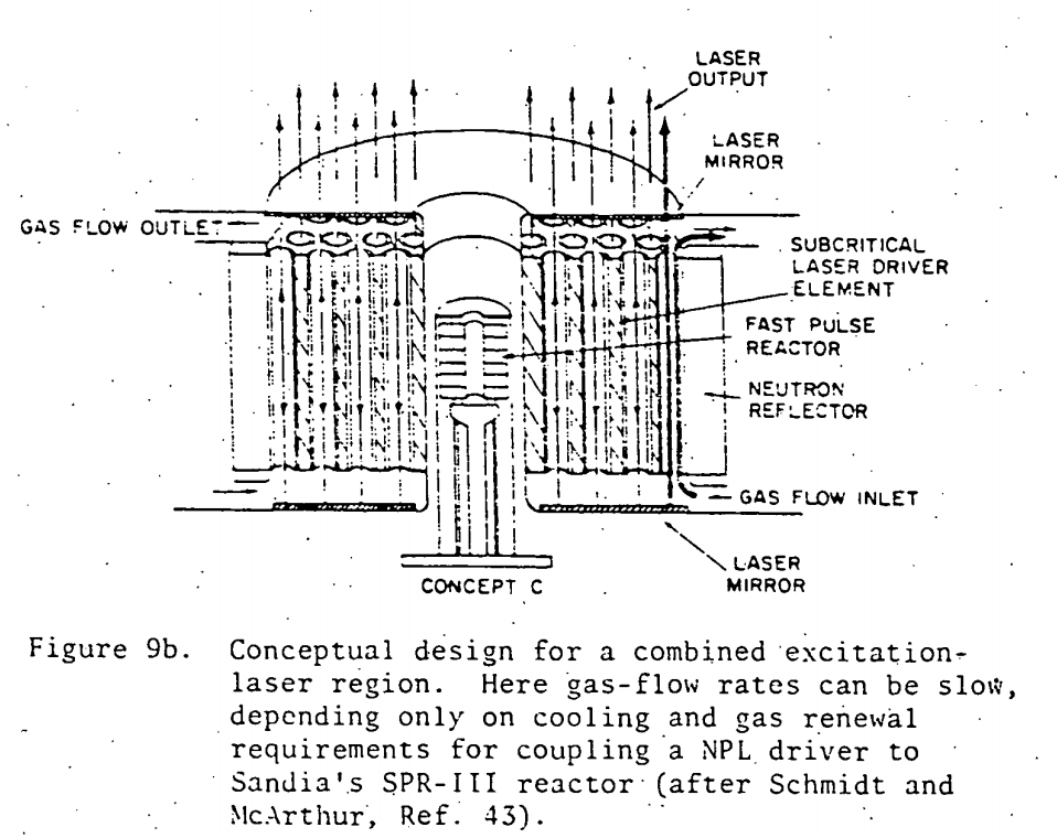
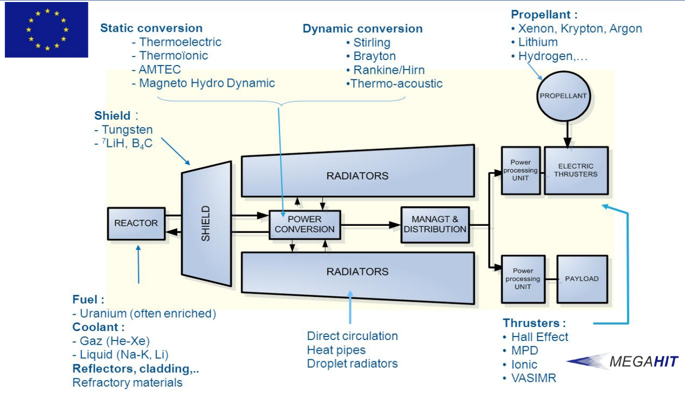


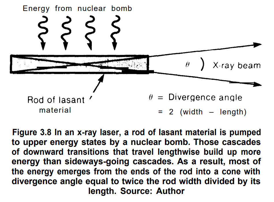

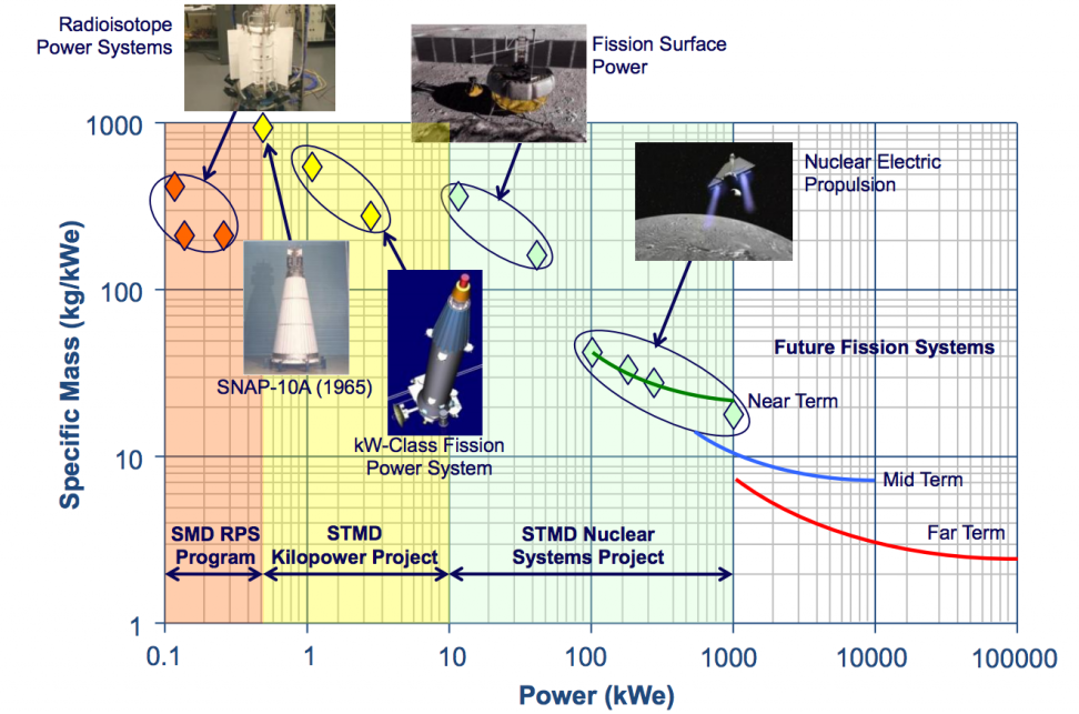


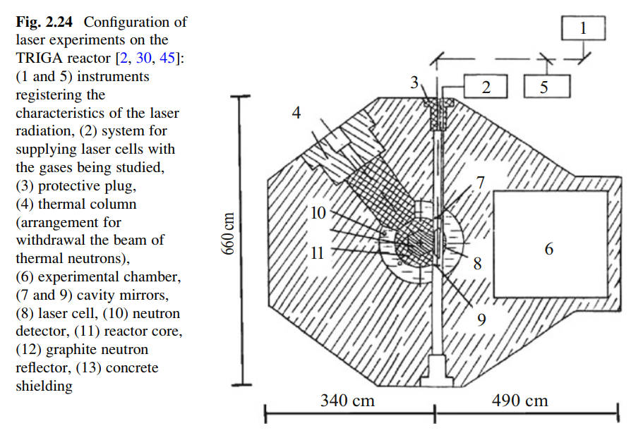
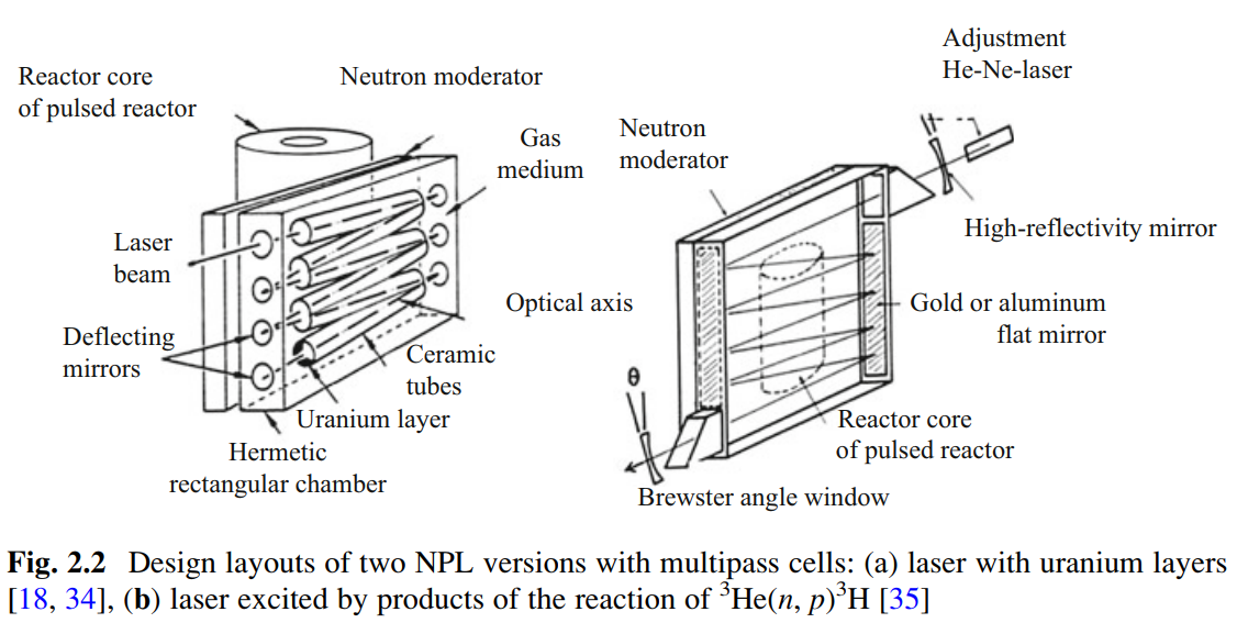
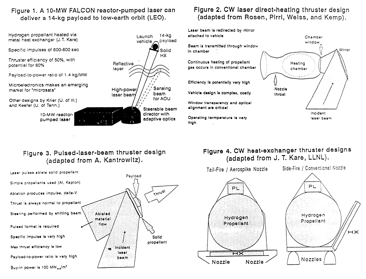

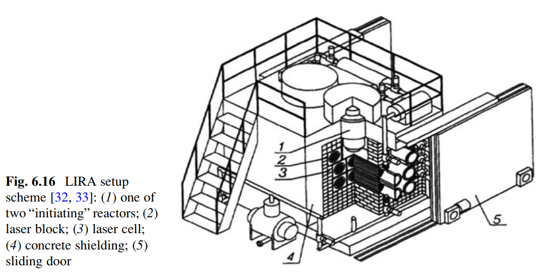


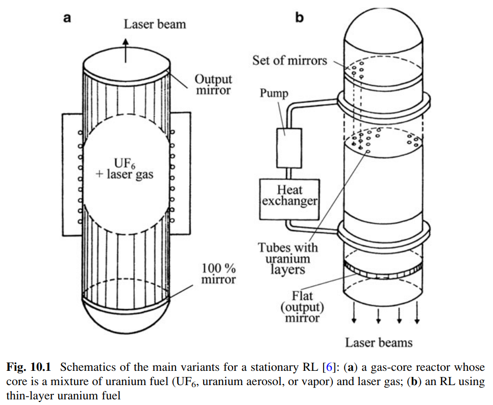


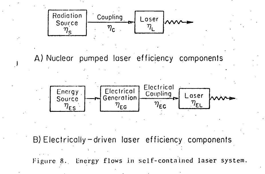


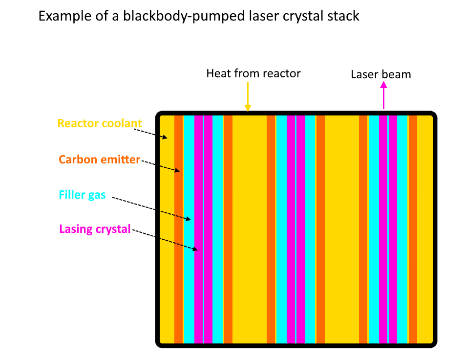


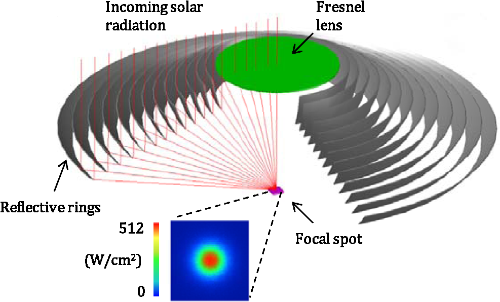


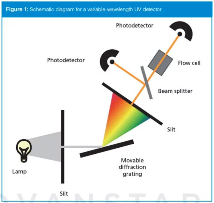

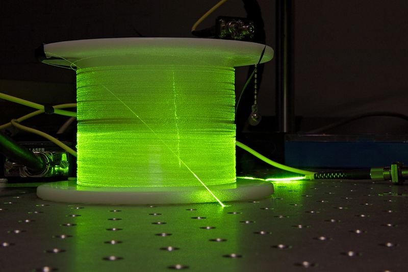


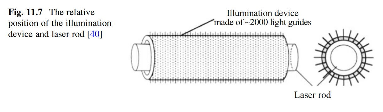


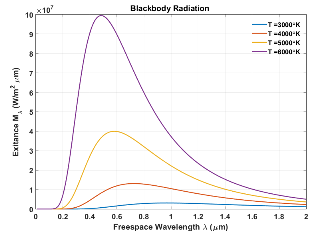


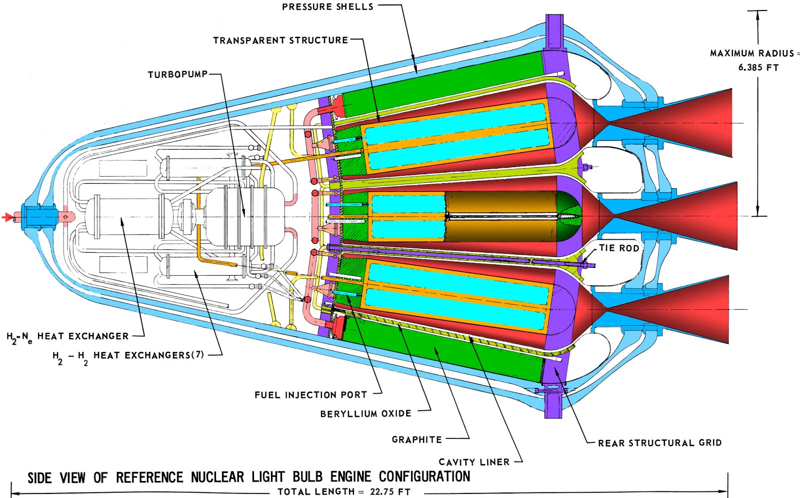


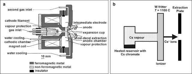
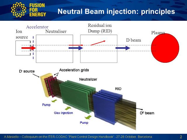
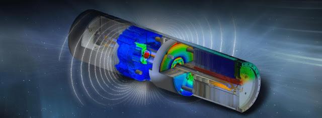
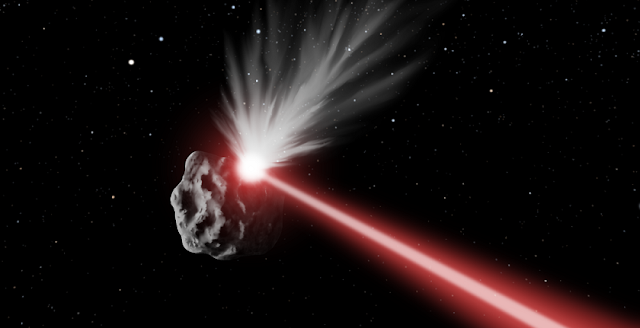
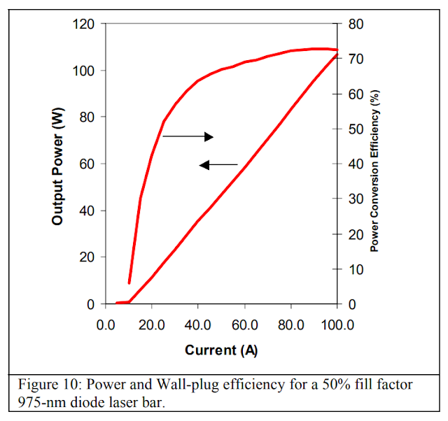


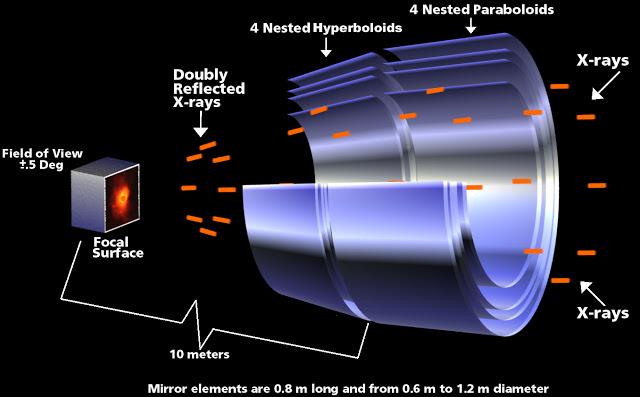
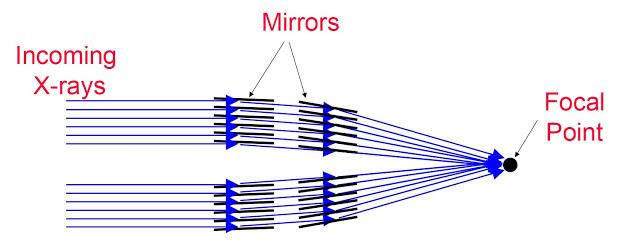
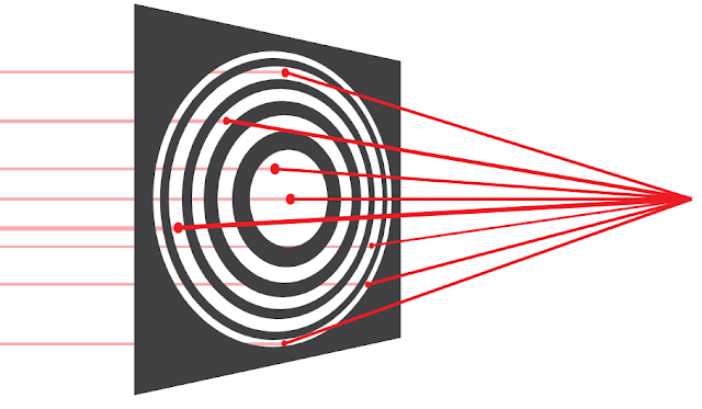


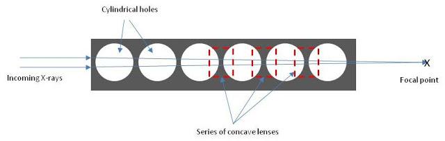
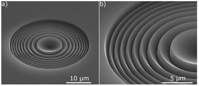
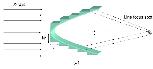
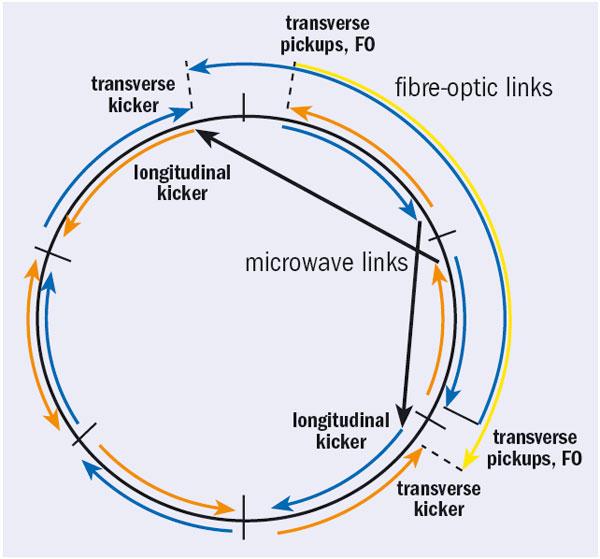
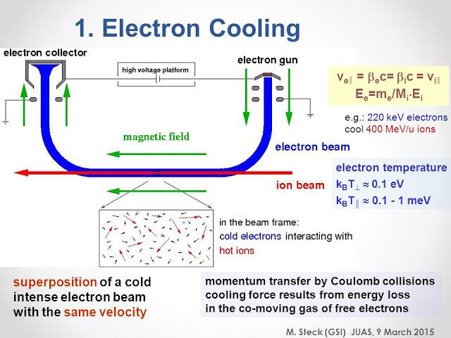
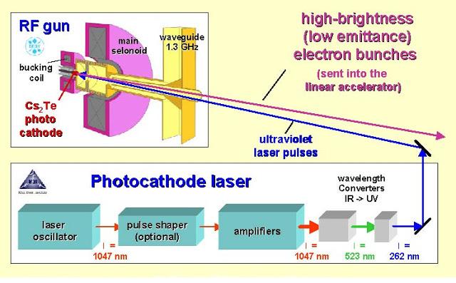

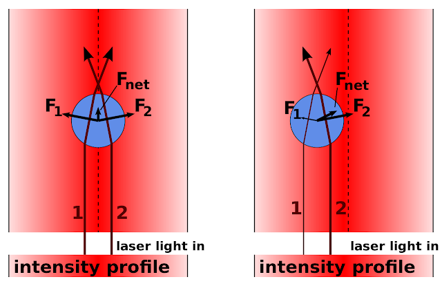

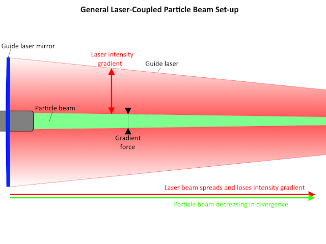
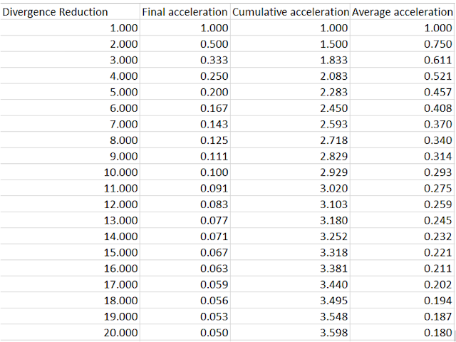
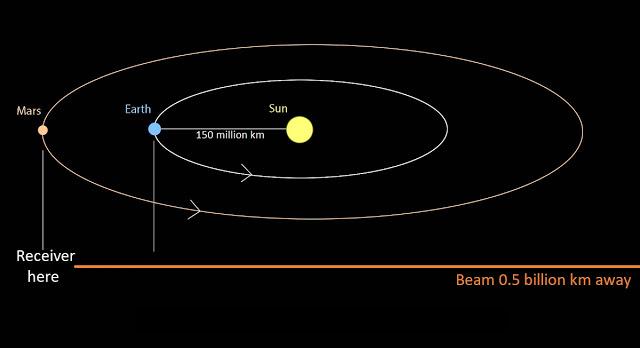
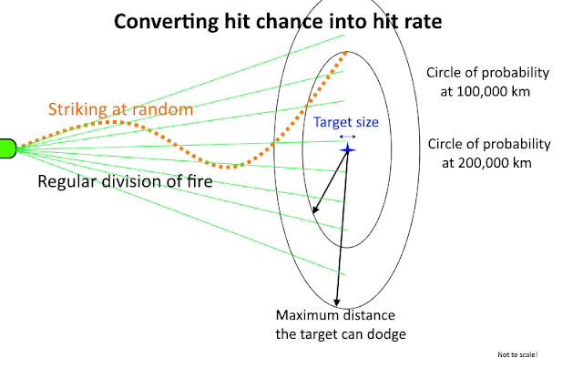
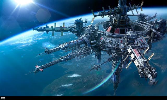
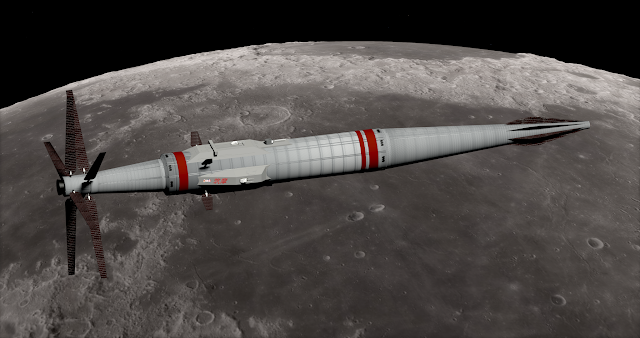

#/media/File:Animation_of_Sycorax_orbit_around_Uranus.gif)
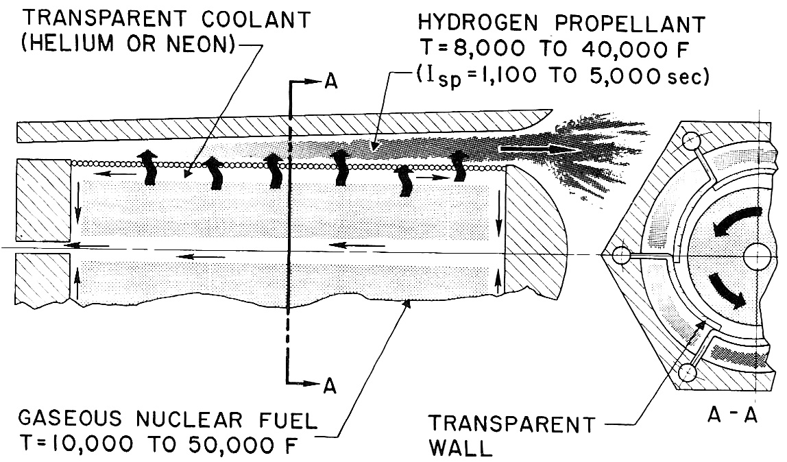
[KSP 1.3.1] Simple Logistics (2.0.2) - Who needs pipes? 2017-10-17
in KSP1 Mod Releases
Posted
Thanks for continuing this mod, @zer0Kerbal