


MatterBeam
-
Posts
1,570 -
Joined
-
Last visited
Content Type
Profiles
Forums
Developer Articles
KSP2 Release Notes
Bug Reports
Posts posted by MatterBeam
-
-
On 11/13/2020 at 7:26 PM, DDE said:
Yes, directly inspired by your own findings, @DDE
-
Both the tether tip and the payload can extend their own cables with maneuvrable drones on each end to prolong the rendezvous. Thing of it like a 'grappling hook' that aims itself at the main tether.
You can also have a tether station with multiple tethers, so you have three or four tether tips to choose from in the space of a few minutes instead of a single pass. The ultimate evolution of this is the bicycle-wheel configuration, where a very large number of 'spokes' carry a circular rim.
Alternatively, you can have multiple whole tether stations, separated by a few minutes on their orbital path, giving you many more opportunities to rendezvous.
-
From the original post: https://toughsf.blogspot.com/2020/07/tethers-all-way.html
Space Tethers: Stringing up the Solar System
All the methods we have used to reach space so far have been subject to the Tsiolkovsky rocket equation - propellant must be ejected and more and more of it is needed to go further.
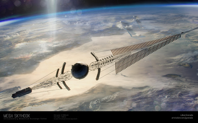 Art above is by Jullius Granada.
What if we could break that equation with rotating orbital tethers?The tether
I have worked with Kurzgesagt to write the following video on the topic of this post: https://www.youtube.com/watch?v=dqwpQarrDwk.It is highly recommended that you have watched it first before continuing, as it is an excellent introduction and explanation of momentum exchange tethers.
The simple description is that a rotating tether, consisting of a strong cable with an attachment point at the tip and an anchoring counterweight at the center, will be able to catch and throw payloads without requiring a rocket engine. The process of hooking onto a payload to accelerate it into a new trajectory will transfer momentum from the counterweight to the payload, causing the tether to slow down. In reverse, a payload can be caught and slowed down, transferring momentum back into the counterweight and speeding it up. The ability to transfer momentum back and forth is why these structures are also called momentum exchange tethers.
NASA has long studied this option. In this post, we will go into more detail on what is needed to create a functional rotating tether, how it can be used and what its potential effects are on space travel and industry could be.
The mechanics
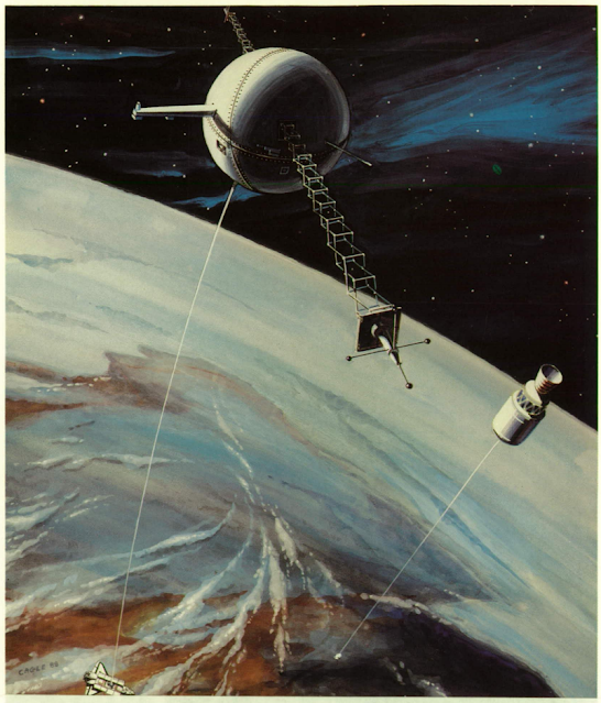
Using a tether to move from one orbit to another, in this case LEO to GEO. The idea to use a long tether to climb into space without expelling propellant is an old idea. A huge tower extending up past the atmosphere was described by Tsiolkovsky. It is ironic that the person who first described how hard spaceflight by rocket is, due to the exponential nature of the deltaV equation, is also the person who described the best way to side-step that problem with non-rocket launch.
The material requirements for a full space elevator are extreme. The only practical way to build it would be to use carbon nanomaterials, but extended to a scale of multiple kilometres instead of the micrometres we struggle to produce consistently in a laboratory today. It is why we must turn to something that provides some of the same benefits without the same stringent requirements.
For this, there is the orbital tether concept.
A large object in orbit, such as a satellite, space station, captured asteroid or similar, can serve as an anchor point to extend a strong cable down to a lower altitude. A payload can grab onto the lower end of the cable and climb up to the altitude of the anchor point. This climb does not require the use of propellant.
The simplest design is a stationary orbiting elevator that provides a deltaV benefit based on the difference in orbital velocities at high and low altitudes.

An LEO to GEO elevator. In the example above, an space station orbits at 2,000 km altitude, at an orbital velocity of 6.89 km/s. It performs one orbit in about 2 hours and 7 minutes. The lower tip extends down to an altitude of 200 km. It retains its orbital period but the distance it travels is much less, so velocity is reduced to 5.41 km/s. A circular orbit here is 7.78 km/s, so it provides a 2.37 km/s saving. The upper tip reaches up to 3,860 km altitude. It covers much more distance with the same orbital period, so velocity increases to 8.43 km/s, compared to the 6.24 km/s of everything else orbiting at that altitude. It is a 2.19 km/s boost. In total, we get a 4.56 km/s benefit.
Huge altitude differences are needed to create the potential for significant deltaV savings. Because the lower tip of the tether is travelling at orbital velocity, it cannot extend too far down either; as it would encounter the atmosphere and burn up.
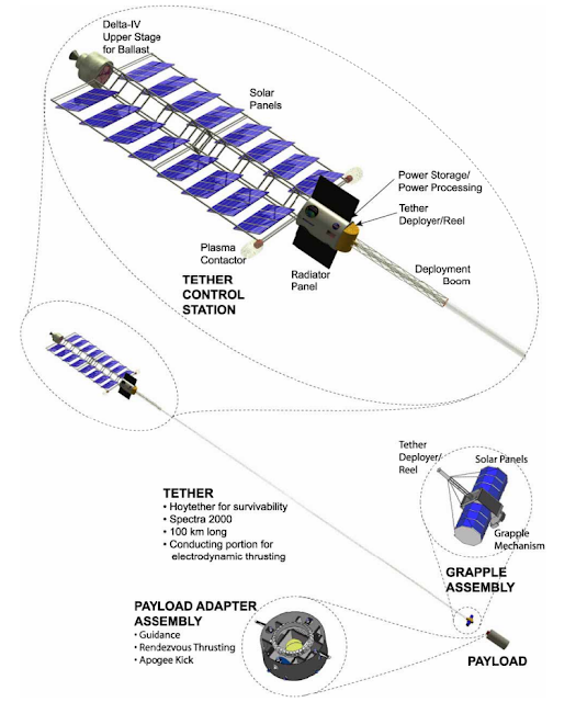
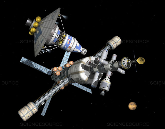
A tether boost facility designed to be launched from a DeltaIV. A rotating tether does away with those limitations. The velocity of its tips and the speeds at which it can capture or release payloads can vary greatly from the orbital velocity of the anchor point. It can be much shorter too.

At its lowest point, the tip of a rotating tether will be travelling at orbital velocity minus the rotation velocity. At its highest point, the two velocities will add up. The length of the tether itself will place the tips at very different altitudes at their highest and lowest points. Moving a payload between these altitudes is an additional benefit.
Let’s imagine a modestly-sized tether orbiting at a high altitude above the Earth. It is 1,000 km long, orbiting at 1,100 km altitude and rotating once every 70 minutes. Its lowest point is 100 km above the surface of the Earth. Its highest point extends to an altitude of 2,100 km. Tip velocity is 1.5 km/s. It is tapered from base to tip to minimize its mass.
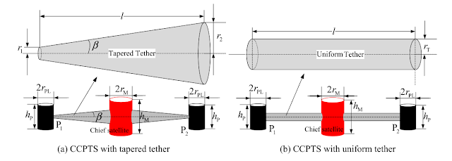
Tapered tethers are the lightest design. Orbital velocity at 1,100 km is 7.3 km/s. At its lowest point, the tether tip will be travelling at 5.8 km/s relative to the ground. At its highest point, this value becomes 8.8 km/s.
If a suborbital craft launched from the ground to try to catch up with the tip at its lowest and slowest, it would need to expend a deltaV of about 6.8 km/s. It can then quickly transfer a payload onto the tether. The payload then starts its 35 minute journey up around to the opposite end of the tether. It experiences an average acceleration of 0.23 g while doing so.
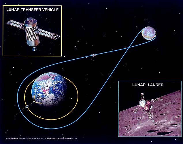
At the top of the tether, it is released into a trajectory that forms an ellipse with its periapsis at 2,100 km altitude and its apoapsis at 13,500 km. It can then expend an additional 1.4 km/s of deltaV to reach the Moon, or about 1.6 km/s to escape the Earth entirely.
If a typical 350s Isp kerosene-oxygen rocket is used, then it needs a total deltaV of about 8.2 km/s to ride the tether to the Moon. Meaning, it has an overall mass ratio of 10.9. However, if there is no tether available, then the deltaV requirement rises to 12.5 km/s and the mass ratio required balloons to 38! The tether is effectively saving 4.3 km/s of deltaV and leading to a much smaller rocket.
The tether can also help with returning from the Moon. The spacecraft swoops down from lunar altitude (384,400 km) to a rendezvous with the tether at 2,100 km altitude. It would be travelling at 9.6 km/s, so it needs to spend an additional 0.8 km/s of deltaV to slow down enough to match the 8.8 km/s velocity of the tether's upper tip. In return, it avoids having to slam into the atmosphere and instead is swung down for much gentler aerobraking. The weight savings from having a thinner heatshield could more than make up for the propellant consumed, especially if this is a reusable vessel.
Note that tethers do not have a single velocity for catching and releasing payloads. It is in fact a range of velocities, from zero up to the tip velocity. For capture at lower velocities, a payload can aim to intercept the tether at a point closer to the base of the tether. Halfway up the tether means a redezvous at half the tip velocity. The same goes for release; not releasing from the tether tip means a lower velocity. You can imagine a vehicle launching up from the ground to catch the tether tip at its lowest point, and instead of swinging around to the other side, just slowly climbing up the tether until it can hop off from the anchor station. This puts it in an orbit parallel to the anchor station, which is great if you are not trying to fly off to the Moon or beyond.
However, making use of this flexibility means adding a way to prevent the unused length of the tether from striking the payloads coming in for a rendezvous, as well as providing structures that allow payloads to climb up and down the tether (although they can be as simple as a pulley and cables).

The ISS regularly is regularly reboosted against the effects of drag. And of course, none of these deltaV savings are for ‘free’. Accelerating payloads means the tether will slow down. If it slows down too much, it will de-orbit itself. The momentum lost with each catch-and-release operation must be recovered either by absorbing momentum from payloads being slowed down, or by using its own propulsion system.
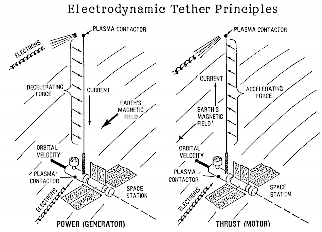
A major advantage of an orbital tether is that you do not have to immediately recover that momentum - it gives time for slower but more efficient propulsion systems like a solar-electric thruster to gradually accelerate the tether. A chemical propulsion system limited to 450s of Isp is not needed as the acceleration can be done over time with something that has thousands of seconds of Isp. The propellant needed to run the tether’s engines is greatly reduced. Even more interesting is the possibility of propellantless propulsion, such as electrodynamic tethers that push off the magnetic fields around a planet.

Electrodynamic tether reboost. Another advantage is that the tether can ‘store’ excess momentum. It can accelerate itself to a more energetic orbit with a higher velocity. For example, a tether in a 2,000x2,000 km circular orbit could accelerate by 1 km/s to reach a 2,000x9,565 km orbit. It can still capture payloads at the same 2,000 km altitude, but it will have an additional 1 km/s of velocity to use. The extra velocity can be used to accelerate the same payloads faster, more numerous payloads to the same speeds or larger payloads than possible before.
Tether masses and velocities

Tether structure and materials for the early TSS-1 experiment in orbit. The tether materials determine how fast the tips can rotate. Each material has a certain characteristic velocity, given by:
- Characteristic velocity = (2 * Tensile Strength / Density)^0.5
Characteristic velocity is in metres per second.
Tensile Strength is in Pascals.Density is in kg/m^3.Steel is strong, with a maximal strength of 2,160 MPa for AerMet 340, but dense, at 7,860 kg/m^3. This gives it a characteristic velocity of 741 m/s.
The aramid fiber Kevlar is stronger and lighter, managing 3,620 MPa with 1,440 kg/m^3. Its characteristic velocity is 2242 m/s.
The strongest material we can mass-produce today is Toray’s polyacrylonitrile fiber T1100G. It can resist 7,000 MPa while having a density of 1,790 kg/m^3, so its characteristic velocity is 2,796 m/s.
If we can describe the tip velocity as a multiple of the characteristic velocity, then we can use a much simpler equation to work out how much a tether will mass. We’ll call this the Velocity Ratio or VR.
For example, 1.5 km/s is a VR of 2.02 for steel but only a VR of 0.54 for T1100G.
The tether mass will be directly proportional to the payload mass. If it has to pull up a 1 ton payload, it will be ten times heavier than if it only needs to pull on 100 kg payloads. Using the VR, we can calculate the tether mass ratio using this equation:
- Tether Mass Ratio = 1.772 * VR * e^(VR^2)
Tether Mass Ratio is a multiple of the payload mass, in kg.
VR is the Velocity Ratio.Using the previous example, a 1.5 km/s steel tether will have to be 211.8 times heavier than its payload. A T1100G tether would only be 1.28 times heavier than its payload. This is a significant difference. The e^(VR^2) portion of the tether mass equation highlights just how important it is to use strong yet lightweight materials and to keep the tip velocity close to the characteristic velocity.
Here is a graph showing how tether mass increases with the Velocity Ratio for different materials:
It should be noted that all of these calculations are for a tether with no safety margins. Any sort of variation, such as vibrations from the counterweight or an imperfect capture of the payload, would snap it. A minimal safety margin might be 50%. Crewed spacecraft might demand a 200% margin or more. What this means in practice is that the maximum payload the tether could handle is reduced to create a safety margin.
To overcome the limitations of the tether tip velocities, the tether can move into higher energy orbits. For example, a tether with a 1.5 km/s tip speed starts off in a circular 2000 km altitude orbit moves itself into a 2,000x1,000,000 km orbit. It can still capture payloads at the same altitude but it now does so at a velocity of 9,391 m/s instead of 6,897 m/s. This gives it 36% more momentum to give, and it can release payloads at a velocity of up to 10,891 m/s relative to the Earth. This is beyond the escape velocity at that altitude! If the tether had stuck to its initial 2000km circular orbit, its tip speed would have had to be 4 km/s instead, which would have meant an exponentially higher mass ratio.
As the tether collects and releases payloads, it must adjust the distribution of its mass to maintain its center of rotation.
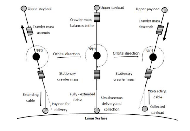
Adjusting the tether with a moving counterweight on a 'crawler'. This can be done by shifting the counterweight, moving additional masses up and down the tether, changing the length of the tether using motors and/or having a dynamic suspension system that also helps dampen vibrations.
In later sections, we will go through the various ways tethers can be used and combined to cover the entire Solar Systebm.
Skyhook
The most immediately beneficial application of an orbital tether is the form of a Skyhook. This is a well-studied concept that dips the tether tip as low and slow as possible into the upper atmosphere, so that a suborbital craft can catch up to it, rendezvous, transfer a payload and then fly away.The skyhook process from Hoyt. Getting off Earth and into orbit is a massive task. It requires that over 9 km/s of deltaV be delivered in one chunk, by a high thrust propulsion system. Chemical rockets can do this, but they end up as balloons of fuel with a small payload on the tip.
A skyhook can help reduce deltaV requirements where they are hardest to deliver: at the end of a tiresome fight against Earth’s gravity. Because of the exponential nature of the Tsiolkovsky rocket equation, the last 1 km/s of deltaV costs much more than the first 1 km/s. The savings enabled by a Skyhook are therefore disproportionately high.
Imagine a 200 km long tether anchored to a station orbiting at 400 km altitude. Its tip speed is 2.4 km/s. This means it travels over the ground at 5.3 km/s at its lowest point, and swings above at 10.1 km/s.
A rocket trying to catch up with this tether at its lowest point must deliver 5.3 km/s of horizontal velocity, but also about 1.5 km/s to reach a 200 km altitude as well as make up for drag and gravity losses on the way up. Its deltaV requirement becomes 6.8 km/s. With kerosene and oxygen propellants delivering an average Isp of 330s, it would need a mass ratio of 8.17. This is well within the reach of a single-stage vehicle, even with margins to return and land vertically for reuse.
For comparison, a kerosene/oxygen-fuelled vehicle that must make orbit would need 9.5 km/s and a mass ratio of 18.8. It would need multiple stages and it would be difficult to create deltaV margins for recovery. The tether-assisted rocket is 2.76 times smaller and lighter for the same payload!
But that’s not all.
The tether swings around and launches its payload into a 400 x 35,800 km orbit. This is also known as a geostationary transfer orbit (GTO) - an orbit where a rocket would only need an extra 1.5 km/s to turn into a 35,800 x 35,800 km geostationary orbit.
The tether’s top-side boost is worth another 2.4 km/s. If it has to be delivered by the same vehicle that must reach orbit on its own, deltaV requirements would add up to 11.9 km/s. With 330s Isp propulsion, this means a staggering mass ratio of 39.5. Modern rockets get around this by fitting their upper stages with more efficient rocket engines, but they still take a huge hit to their payload capabilities when launching to GTO instead of LEO. ULA’s Delta IV Heavy could launch 28 tons into LEO but only 14 tons into GTO.
We could do better. A faster tether that dips deeper into the atmosphere is possible, further reducing the deltaV requirements for meeting it and reducing the constraints on the vehicle we use.
The lowest a tether tip could reasonably go is 50 km in altitude, making it 200 km long if it orbited at 250 km altitude. It could be pushed up to 6 km/s in tip speed, bringing its tip to a mere 1.7 km/s relative to the ground at its lowest point and to 13.7 km/s at its highest point. We can call this design a ‘Hypertether', inspired by works like HASTOL.
HASTOL. We don't really want the plane to exit the atmosphere. 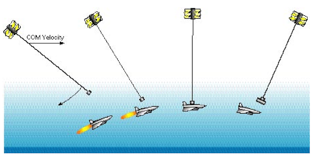
1.7 km/s corresponds to Mach 5 at this altitude. We have had aircraft reach these speeds and altitudes for decades, under rocket power. We have developed hypersonic scramjets that can sustain these speeds much more efficiently too. A large aircraft could meet a Hypertether using existing technologies reliably, without needing a lot of propellant or excessive thermal shielding. The exponential mass ratios that make rockets so expensive no longer come into play. Hypersonic rendezvous vehicles could climb to this altitude using engines with Isp exceeding 4000s (using hydrogen fuel), fly long enough to attempt multiple rendezvous with the tether (one attempt per tether rotation period) and land, ready to fly again within the hour.
The downside to this approach is that the mass ratio of the tether itself becomes unwieldy. At 6 km/s, even T1100G tethers require a mass ratio of 379. The result is huge tethers in orbit needed to handle even the smallest of payloads. With a 200% safety margin, a 1 ton payload would need a 758 ton tether in these conditions. Launching such a mass into space and fitting it with an appropriately sized counterweight and anchor point would require hundreds of launches to break-even with the cost.
A staged tether can get around some of these difficulties.

Just like a rocket, a tether can be broken up into stages. Each stage uses the tip of the previous tether as its anchor point. If two 3 km/s tethers are staged, then they could achieve a combined 6 km/s tip velocity. However, each stage only needs a mass ratio of 6, with T1100G. A 1 ton payload would need 1x6: 6 ton first stage tether and a (1+6)x6 : 42 ton second stage tether. Add a 200% safety margin and it would still be an overall mass of 84 tons, which is much lower than the previous 758 tons for a single tether.
Many difficulties must be overcome with this design. The first is the need to absorb any lateral movement which could cause tether sections to run into each other. The second is to create a stable joint that can operate under huge stresses. Using some of the mass savings from a staged tether design to alleviate these problems is recommended. Finally, each tether stage will be relatively short, leading to high centrifugal forces being imposed. If a 200 km long tether is divided into two 100 km sections, each rotating at 3 km/s, then payloads would be subjected to an acceleration varying between 9 and 18g. Much longer tethers would be needed for human travellers.
Overcoming these difficulties would yield a flexible Hypertether with exceptional performance but low mass.

A huge, slowly rotating skyhook would not look much different from a section of space elevator near the ground. The ideal skyhook, as originally conceived for science fiction, uses multiple stages so that its combined tether tip velocity matches its orbital velocity. It would become stationary relative to the ground with each rotation. This means a combined 7.7 km/s for a tether orbiting at 250 km altitude. No rendezvous vehicle is needed; payloads would simply sit on the ground and latch onto the descending hook from the sky.
A huge number of additional challenges face this ‘perfect Skyhook’ design, ranging from the need to prevent unpredictable air turbulence from smashing tether stages into each other, to needing thermal protection for tethers that accelerate to multiple km/s while coming up through the thickest portions of the atmosphere.
High performance skyhooks around Earth will mostly aim to lift payloads up from the ground and out into space. They are likely to run at a permanent momentum deficit; propulsion is essential. Obtaining propellant is an obstacle, as are the power requirements.
The simplest solution is to sacrifice a portion of each payload using the tether to carry propellant. Low performance tethers that sit at high altitudes and with low tip velocities will make this a very expensive option. This is because they make rendezvous vehicles work hard to get to them. If a 1,000 ton tether station accelerated a 3 ton payload by 3 km/s from rendezvous to release, it would lose 9 m/s itself. Accelerating 1000 tons by 9 m/s using a 3,000s Isp engine requires about 305 kg of propellant. This means that, roughly, for every 9 payloads accelerated by the tether, a 10th launch is needed for refuelling. High performance tethers have it worse. They lose more momentum proportionally with each payload they accept, because of their higher tip speeds. Accelerating a 3 ton payload by 12 km/s slows down a 1,000 ton tether by 36 m/s, requiring 1,223 kg of propellant to recover! Thankfully, they make travel to space so much cheaper that sacrificing every third payload for propellant still makes for an overall saving over rockets.
Extraterrestrial sources of propellant can be much more interesting. It normally takes less deltaV to move propellant from the Moon to LEO than it takes to move it up from the ground to LEO, at about 5.8 km/s vs 9.5 km/s. With aerobraking, the deltaV required to return from the Moon’s surface to Earth orbit is reduced to 2.8 km/s. Lunar sources of propellant remain interesting even when we adjust the deltaV requirements to account for the tether helping out. A tether with 3.1 km/s tip velocity would reduce the deltaV needed to lift off from Earth’s surface and enter into Low Earth Orbit to 6.4 km/s. It would also reduce the deltaV needed for a spaceship to launch off the Moon and enter Low Earth Orbit to 2.8 km/s. This keeps lunar sources of propellant the better option over terrestrial sources.
Another advantage of extraterrestrial propellants for tethers is that capturing them ‘recharges’ the momentum of the tether. Catching 1 ton of propellant coming in at 3 km/s would accelerate a 1,000 ton tether by 3 m/s. Using that propellant for a 3,000s Isp thruster would further accelerate it by 29 m/s. That propellant is worth 10% more than expected!
The absolute best propellant source of Skyhooks around Earth is the atmosphere itself. Atmospheric gas scooping is discussed in full detail here. A tether tip dipping into the atmosphere can ‘cheat’ the gas scooping retention equation by collecting gases at a lower velocity than the tether station’s orbital velocity. For example, a tether at 250 km altitude rotating at 3 km/s would collect gases at a velocity of 4.7 km/s. If a 3000s Isp engine running on nitrogen and oxygen is used, up to 84% of gases collected can be retained. The gases retained can then be fed to rockets using the tether, turning it into an orbital fuel depot.
What’s more exciting is that it removes the restriction from the tether to have high Isp engines in the first place. They are bulky and power-hungry equipment. A tether that only aims to regain velocity would be satisfied with 0% gas retention. Lighter, simpler propulsion options like nuclear thermal rockets, with an Isp of just 480s, become acceptable. Alternatively, we could use hydrogen-oxygen chemical rocket where payloads coming up the tether provide 12% of the propellant and the remaining 88% is oxygen collected from the atmosphere.
Better than any propellant source is not having to use any propellant. This is important for very high altitude tethers that do not meet the atmosphere. Electrodynamic propulsion pushes off the magnetic field around Earth. It only consumes electricity. Although the thrust per kW is very low, it is a reliable and already tested option.
Powering all these propulsion options is another concern. Ideally, a tether station would want a compact and long-duration power source like a nuclear reactor. Solar panels are also available, but they require hefty energy storage solutions from the periods where the tether is in the Earth’s shadow, and the drag from the exposed panels adds to the momentum loss over time. Between these two options is the possibility for beamed power. Whether it is from the ground or a space station far above, energy can be transmitted over microwaves or a laser beam to the tether station, where it is converted back to electricity with high efficiency.
Moonhook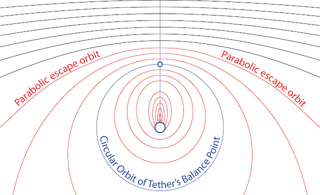
From Hop David's excellent blog. Getting off the lunar surface and into orbit involves much lower velocities than on Earth. There is no atmosphere imposing a minimum orbital altitude either. For these reasons, there are many proposals to install a rotating tether around the Moon first.Such a Moonhook would only need a tip velocity of about 1.5 km/s when orbiting at a 400 km altitude.
Because of the lower velocities involved, it can be very lightweight, and easy to transport into a lunar orbit from Earth. There would be no erosion from passing through gases, and it would only have to avoid lunar mountains (up to 6km high) when coming down.
This tether can help transfer payloads to the lunar surface, but also to other interesting locations, such as the L1 or L2 Lagrange points. It could be the centerpiece of a cislunar economy, and unlike the ‘lunar elevator’ concept, it does have to extend across hundreds of thousands of km to be useful.

Phobos elevator suggested here. Reasons for a moonhook also apply to other moons. Phobos is a popular destination for small moonhooks, enabling access to the martian surface for 2.14 km/s.
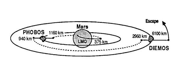
It could relay work with a tether around Deimos to enable a zero-propellant transfer into and out of the martian system.
Interplanetary trajectories
As mentioned in the previous section, tethers can easily fling payloads far beyond Earth.
Here is a table of tether tip velocities needed to place payloads on Hohmann transfer trajectories to different planets:

Injection DeltaV is the velocity increase in meters per second that the payload must receive to enter a trajectory that takes it near the destination. Another propulsion system is needed to actually slow down once it arrives.
The mass ratio calculations are done for T1100G cables. You will notice that some destinations, like Mars or Venus, are well within the capabilities of reasonably sized tethers. Mercury or Ceres can be reached with very heavy tethers. Going beyond Jupiter strictly necessitates the use of staged tethers, with Neptune probably off-limits for an Earth-based tether.
The DeltaV values listed above are for Hohmann trajectories. For the Outer Planets, minor increases in deltaV (8400 m/s instead of 8200 m/s for Uranus, for example) were selected to enable missions that took less than 10 years to perform. Tethers can speed up travel between planets, by entering payloads into higher energy trajectories.
Here is another table showing how much travel times (in days) can be reduced by tethers with 4, 6 and 8 km/s tip velocities.
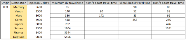
Venus and Mars are the greatest beneficiaries of an extra boost from a faster tether. Mars sees up to 5 times shorter trips when using an 8 km/s tip velocity tether. When the injection deltaV becomes more demanding, the benefit is reduced.
A good idea is to have spacecraft using tethers employ their own propulsion system. They can act as an additional ‘stage’ with their own mass ratio between propellant and payload. As we calculated before, staging massively reduces the difficulty of reaching a certain velocity.
Here is an example:
A spaceship using 450s Isp chemical rockets loads up 2 kg of fuel for each 1 kg of dry mass. This gives it a mass ratio of 3 and a total deltaV of 4850 m/s. It performs a rendezvous with a 6 km/s two-stage tether made out of T1100G cables. The first tether stage has a mass ratio of 12, to get a tip velocity of 3000 m/s and a 100% safety margin on top. The second tether stage also has a mass ratio of 12.
Mass ratio of this system is 3 x 12 x 12: 432. The final velocity of 10,850 m/s enables trips to Jupiter in as little as 325 days, or to Uranus in 1551 days. A two-stage tether that tries to achieve this velocity would have had a mass ratio of over 22,000, while a single stage tether would have needed a ridiculous 23.8 megatons of cables for each ton of spaceship.
Working through calculations like these really helps highlight just how similar a tether stage and its characteristic velocity is to a rocket stage and its exhaust velocity.
Tether trains and interplanetary networks
A tether can hand over a payload to another tether.
These tethers can be in different orbits, and have different tip velocities, so long as the relative velocity falls to zero during a rendezvous. Three interesting scenarios for tether handovers can be considered:
-Exchange between circular orbits
A tether in a low orbit can fling a payload up to an altitude that intersects with a tether in a higher orbit. It is caught and further boosted from this higher orbit. Or, payloads can be sent down from the higher tether.
Here is an illustrated example:
It can work best when the higher tether is a geostationary space station, or these tethers are transporting payloads between different moons around a gas giant like Jupiter. The most interesting aspect is that the tethers can keep each other from losing momentum, so long as the masses they exchange are balanced. The lower tether is naturally larger, as it has to send payloads up with a greater velocity. It could set up a ‘train’ of many momentum-neutral exchanges with several tethers.
-Exchange with eccentric orbits
In this exchange, one of the tethers is in a low circular orbit and the second tether is in an eccentric orbit with the lowest point (the periapsis) intersecting the first tether’s orbit.
Here is an illustrated example:
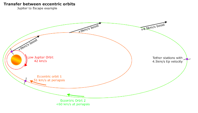
The main advantage is that the tether’s own velocity is added to the boost it can provide a payload. Multiple tethers can be used in sequence, bridging the velocity gap between a tether in a low circular orbit and a very eccentric, near-escape orbit. Low Jupiter Orbit at 42 km/s and Jupiter Escape Velocity at 60 km/s are separated by an 18 km/s gap. Three tethers with tip velocities of 4.5 km/s can relay a payload between them. It does not have to be done all within the narrow window where tethers are all lined up at the lowest point of their respective trajectories. The transfer between orbits can be done one by one.
The tether in the lowest orbit accelerates a payload at 4.5 km/s. It is received by a second tether with a tip velocity of 4.5 km/s. The combined boost is 9 km/s. This is done again, to reach a third tether station that is on a near-escape trajectory, with a periapsis velocity of just under 60 km/s. Any extra boost from this third tether would allow a payload to escape into interplanetary space. A full 4.5 km/s boost can put it on a trajectory that sends it all the way back to Earth.
Using tethers like this will put the deep gravity well of Jupiter on the same level of accessibility as Mars or Venus. The energy-intensive transfer of crew or cargo up and out of Jupiter can be compensated for by slowing down equal masses of ‘junk’ such as iceball comets or discarded asteroids.
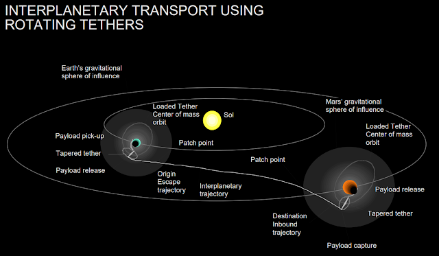
We can also expand the use of ‘tether trains’ to interplanetary space. Stations orbiting the Sun on circular or eccentric orbits could pass payloads between them for ‘free’, so long as momentum exchanges are balanced.

A tether attached to a small body, as envisioned here. These tethers can be anchored to asteroids, moons or mobile bases, much like the slow Aldrin Cycler concepts. Payloads can hop between tethers at these points gaining or losing velocity.
A cycler station makes a trip between Earth and Mars on a regular orbit. Cyclers are most interesting as they perform orbits that take many years, but with tethers, they can send payloads between them much faster.
Moving between cyclers in this manner can take on aspects of a train stopping between towns, especially if the cyclers gain large enough populations to become noteworthy destinations on their own. This can lead to a ‘Wild West’ aesthetic, or fulfil the need to visit new locations without having to cross interplanetary distances.
A Solar System tethered together
A switch in transport of payloads from expensive, slow, propellant-consuming rockets to rapid, low to zero-propellant tethers would have an outsized effect on human expansion into the Solar System.
Human passengers will see great reductions in travel times. The combination of an initial boost from a tether, with deltaV provided by a spaceship’s propulsion system, will connect the Inner planets within a matter of weeks. Tethers provide the option to collect propellant more easily, which means those spaceships can afford to spend a lot more propellant than they otherwise could, in turn making travel even faster. Even the Outer planets could be reachable within a few months of travel time. That’s a great step up from multiple years. Enough perhaps to prevent distant colonies from becoming the destination for a ‘once-in-a-generation migration’.
Cheaper, quicker travel for humans means that automation is not needed as much. Machinery doesn’t have to work for years on end without maintenance, as a repair crew could arrive regularly. A more mobile population means that space becomes open to less skilled, less experienced workers to fill in job positions wherever they appear, instead of every station or outpost having to rely on multi-skilled workers that can handle prolonged isolation. More people moving around means better chances that ‘extras’ like luxuries and personal services can be accommodated, improving living conditions and so on, in a positive feedback loop.

Inert cargo will also benefit from tether transportation. High value goods can be exchanged quickly. A latest generation computer processor wouldn’t have to spend years being exposed to cosmic rays before it reaches a colony around Jupiter as an out-of-date and damaged product. Profits can be made on platinum ground metals a few weeks after they are mined; this means adventurous asteroid mining companies don’t have to hold onto cash reserves so that they can operate for months in between deliveries. They can be smaller, leaner and take more risks.
On the other hand, larger payloads can be moved at the same speed with tethers for much less cost. An exchange between two tethers, one on Mars and one on Earth, can take the regular minimal-energy Hohmann trajectory. However, far less propellant would be needed (if any at all, with momentum-neutral exchanges). The payloads would not need any engines, heatshields or large cryogenic propellant tanks. With the use of tugs to maneuver the payloads into a rendezvous at either end, they won’t even need expensive guidance systems. Such cheap travel opens up many new possibilities. Asteroid mining usually considers elements like iron and aluminium to be ‘wastes’ as their value is too low to be worth moving around. Their only use would be at the site they are extracted from. This no longer has to be the case; a much larger fraction of an asteroid becomes exploitable. A beneficial side-effect is that accessing these low-value resources to build up a colony in a remote corner of the Solar System becomes even more affordable.

Complete this scene with a spinning tether in the background. Large, slow payloads that can easily be outrun by tether-boosted spacecraft opens the door to piracy. A better transportation system helps with the methods discussed in these previous posts. A ‘pirate tether’ can fling spacecraft into intercepts with payloads in transit. Criminal ports would have higher performance tethers to catch diverted goods from odd angles and high velocities. This is especially useful for stealth craft that can use a tether to boost into a trajectory without announcing themselves, and don’t want to reveal the location of their safe haven by slowing down using rockets.
Anything criminals can do, the military can do better. Tether boosts means warships are closer to targets than before. Reduced reliance on onboard propulsion for deltaV means that more mass can be dedicated to armor and weapons instead of propellant tanks. Also, as mentioned before, a secret network of tethers can be employed to move stealth craft around the Solar System. Munitions launched like this can be smaller and easier to hide too.
Further developments
Everything mentioned so far is only the start of what is possible with tethers.
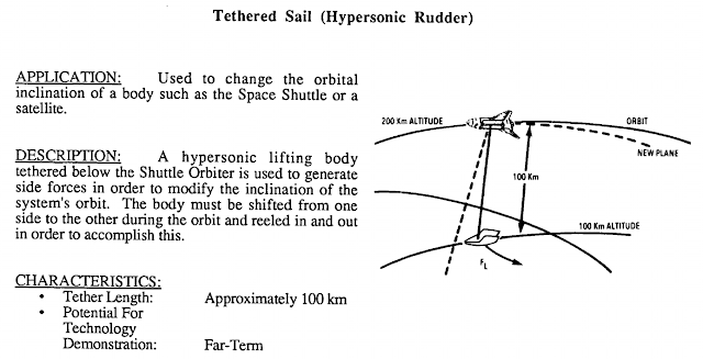
The use of tethers as aerodynamic devices is under-explored. Their use and performance can be expanded over time, as new ideas appear or better technologies are matured.
We could consider a hybrid of a stationary and rotating tether. A rotating hub could be installed at the lower end of a very long stationary tether. It would collect a payload and transfer it to another rotating tether at the upper end by climbing up a stationary segment. The main advantage of this hybrid tether is that it can greatly extend the use of small, low velocity rotating tethers, while also not having to fully cover the distance to the destination like a simple stationary tether would have to.
Supermaterials can also be considered. Tethers don’t need carbon nanotubes to function, but they can make great use of them. The characteristic velocity of graphene (130 GPa strength, 2267 kg/m^3) is 10,709 m/s. A tether to payload mass ratio of 10 enables a tip velocity of 12.3 km/s. A staged tether can get this up to 24.3 km/s with a total mass ratio of 100. That’s enough to fling a payload out of Low Jupiter Orbit with one single tether, or enable trajectories from Earth to Mars in 34 days, or to Saturn in 360 days. Between two tethers, we could see velocity gains of over 50 km/s… the main limitation would become human endurance. Even with a 6g tolerance limit, a tether tip velocity of 24.3 km/s means a minimum tether length of 10,000 km to reduce centrifugal forces!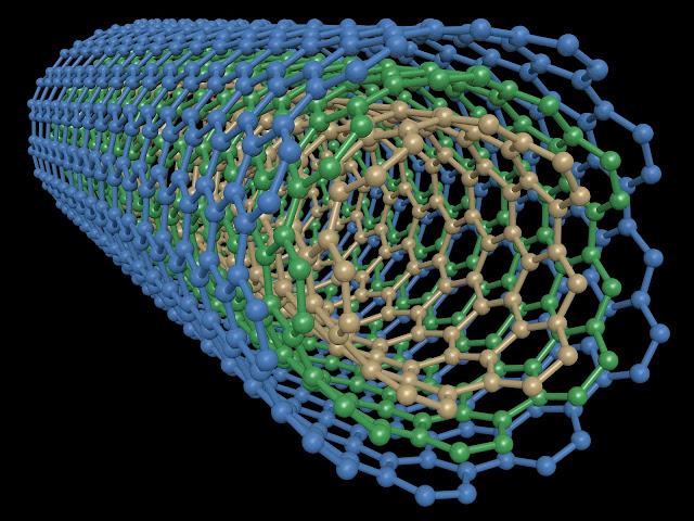
Going further, tether transport networks can be tied into the Inter-Orbital Kinetic Energy Exchange networks for transporting and generating energy, described here. Tethers can set up the exchange of masses, or even convert them into electricity themselves by using an electrodynamic tether in reverse: instead of consuming electricity to push against a magnetic field, using the field to generate a current while braking against it.
Finally note that we haven’t considered the Oberth effect and that tethers can exploit it. Sending a payload down into a gravity well before rapidly accelerating it gives it an extra boost that does not match the momentum lost by the tether. The faster the tether tip, the greater the effect.
-
I have added @zer0Kerbal as an additional author on the SimpleLife page on SpaceDock.
Thanks for these up!
-
@zer0Kerbal Please, do give it a try!
-
Thanks for doing this, @zer0Kerbal
-
On 12/3/2019 at 11:40 AM, DDE said:
@MatterBeam Those macrons aren't exactly going to last long in an atmosphere, will they?
Well, there goes my fusion beam...
The macrons will explode when they touch the atmosphere.
-
7 hours ago, Spacescifi said:
Could not make myself read the entire mini-book of text... but I will try to see if I understand this... feel free to give me the Cliff (short form) notes version.
Macrons?
???
Bits of sand shot at high velocity? Ok now it's starting to make sense.
So you're saying it can be used on a rocket or as a weapon?
The weapon I am less interested in, as just about anything with an engine can turned into a weapon in space.
And if I understand it right... you're saying the sand can be shot across space propel spacecraft far away like some kind of propulsion beam?
So it is a space only tech I gather? Not good enough thrust for launch to orbit, but orbit space speed is stackable so it's all good?
That's all correct.
It's a total of about 7k words though, not that long.
-
This is from the latest Toughsf post: http://toughsf.blogspot.com/2019/11/hypervelocity-macron-accelerators.html
Hypervelocity Macron Accelerators
We look at the various ways of accelerating micro-scale projectiles up to hypervelocity (10-10,000 km/s) and their use in space. Going small to go fast
 Macrons or macroscopic particles are tiny projectiles that sit on the border between the complex structures we see under a microscope and the far simpler molecules where we can count individual atoms.
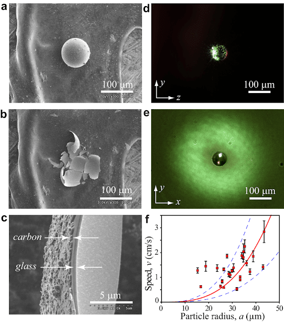 A typical macron is a micrometre in diameter and has a very simple structure. Due to the small size, it exhibits an interesting feature: a very high surface area to mass ratio. A useful number of electrical charges can be placed on a macron’s exterior compared to how much they mass. This feature can be exploited by an electrostatic accelerator.Tiny particles are too small to survive the heating and friction in a railgun, and cannot support large magnetic fields in a coilgun. However, an electrostatic accelerator can bring particles up to high velocities by using a voltage gradient between an anode and a cathode. Charged particles feel a force when placed in between electrodes, proportional to the voltage gradient multiplied by the particle’s charge. When we divide that force by the mass of the particle, we get force divided by mass, which is an acceleration. A macron, with its high charge to mass ratio, will experience a strong acceleration even under small voltages.The velocity gained by a non-relativistic charged particle is easy to calculate:
- Particle Velocity = (2 * Voltage * Charge/Mass)^0.5
The velocity will be in meters per second.
Voltage is in volts.
Charge is in coulombs. Mass is in kg.Charge to Mass ratio, the critical feature of macrons, is in C/kg.Electrostatic acceleration is regularly used today to push small things to great speeds. For example, electric rocket engines such as colloid thrusters shoot out tiny liquid droplets at multiple kilometres per second, which is somewhat similar to how we want a macron accelerator to operate. One design accelerates them to 43km/s. We can also find electrostatic accelerators in the medical field. In fact, the majority of them today are used to generate X-rays for therapy.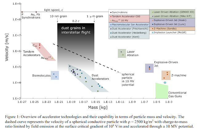 The most powerful electrostatic accelerators are for nuclear research purposes. They operate at several megavolts and are used to accelerate electrons and ions.
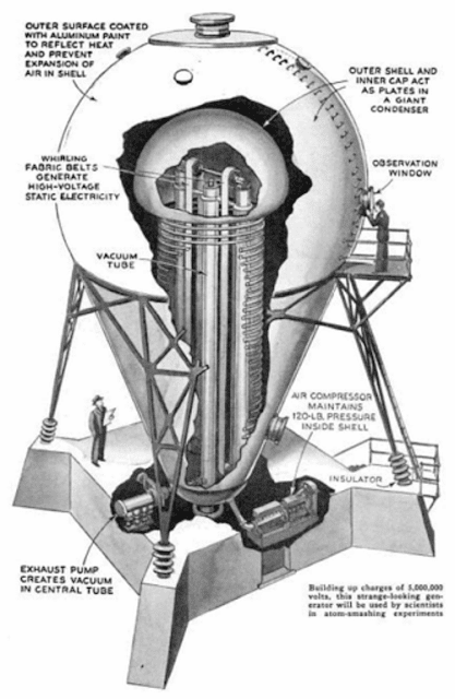 Van de Graaff accelerators have been used to study the impacts of interplanetary dust grains. The original accelerator facility built by Friichtenicht in 1962 was able to accelerate 0.1 μm iron spheres to 14 km/s using a 2 MV potential. We have also designed Cockroft-Walton, Marx and Pelletron accelerators, each different in their way of creating and holding a large voltage potential.How much voltage can be obtained in an accelerator?
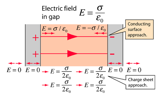 A voltage ‘V’ between two surfaces separated by a distance ‘m’ will create a voltage gradient of V/m. 1,000 Volts across a 1 centimetre gap will give a gradient of 1,000/0.01 or 100,000 V/m. The gradient creates a force that accelerates charged particles, but can also give electrons within the two surfaces enough energy to jump across the gap. The electrons that escape gain energy and slam into the opposite electrode, damaging it and reducing its ability to maintain a voltage gradient.
 Weak voltage gradients are enough to get electrons to jump across a gap filled with a conductor, like salty water. Stronger gradients are needed to cross insulated gaps, like pure vacuum. Charge will accumulate at the tip of any imperfections or contaminants on the surface of an electrode, creating stronger voltage gradients locally and reducing the overall voltage that is possible. Too high a gradient, and enough electrons jump across to create an electric arc. The arcs from too much voltage gradient are lost energy that does not go towards accelerating charged particles. In fact, that energy becomes heat that can burn out anodes and cathodes. A device that operates at the megawatt or gigawatt level will certainly not want electric arcs dissipating that power as heat internally!Single stage accelerator today manage 10 to 15 MV in total. Getting more than that becomes exceedingly troublesome, as voltage multiplying circuits become larger and larger.
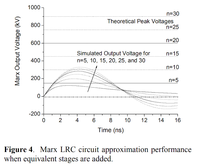 Tandem (or two stage) electrostatic accelerators double their maximum voltage by switching the charge on the particle being accelerated halfway down their length.
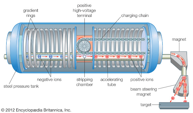 At the upper end, we see Pelletrons with 30 MV. However, the highest voltages are only possible because the electrode gap is filled with a pressurized insulating gas. We cannot use this option inside our macron accelerator as interactions between the charged particle and the gas could create enough friction heating to destroy it. We are therefore forced to rely on simple vacuum. Highly charged macrons cannot be quickly switched from a negative to a positive charge either; the charges that need to move quickly result in destructive currents. Tandem accelerators are not an option either.
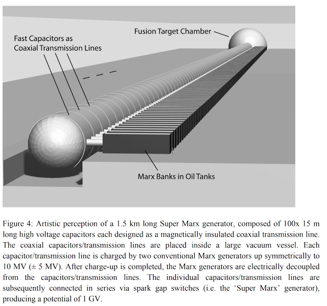 A ‘Super Marx Generator’ was proposed for achieving voltages on the order of 1000 MV; it is 1500 meters long and therefore averages 0.6 MV/m. That design stored a gigajoule of energy. Our macrons do not need that much energy but the length requirements are similar; 100 MV would require 167 meters of capacitors in series.
 Another option is a pulsed staged accelerator. An electrostatic accelerator can be broken down into a series of stages. Each stage consists of a pair of charged plates with a gap between them. The voltage gradient between each pair of plates, assuming excellent vacuum, no contamination and perfectly smooth surfaces, can be on the order of 1 to 10 MV/m, which is far better than the Super Marx generator design. More realistically, 3 MV/m is achievable.
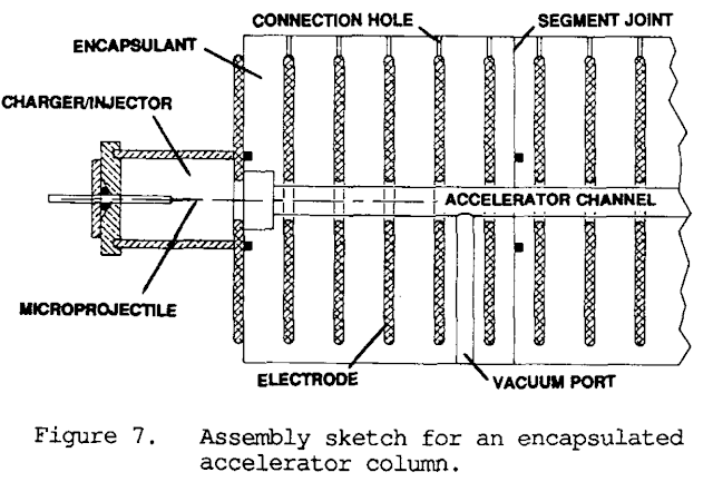 If an electrical current is supplied to the pairs of plates for just the short period where a macron crosses through them, and then it switched off as the macron exits, we end up accelerator driven by pulses of electricity with multiple stages. This design was suggested and demonstrated (for 5 stages) here. The increased voltage gradient means that 100 MV only needs between 10 and 100 meters of length.The downside is that switching the plates on and off is not a perfect process. The switches, likely to be solid state transistors, convert some of the electrical energy into heat and can become a major source of inefficiency.We can also consider a circular accelerator.
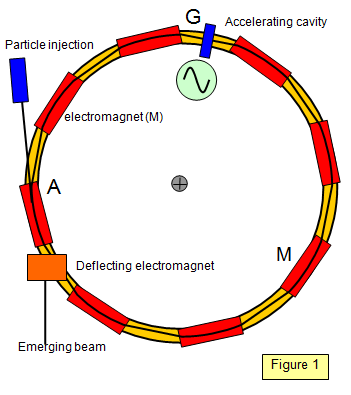 Instead of thousands of stages, a single stage is reused multiple times. The macrons will be bent 180 degrees twice by U-shaped magnets to form a looping trajectory. They gain velocity with each revolution, so there is no ‘maximum voltage’. However, we cannot increase the velocity past the point where the magnets cannot bend the macron’s trajectory.The maximum velocity achievable can be calculated with this equation:
- Maximum Velocity = Bend Radius * Magnet Strength * Charge/Mass ratio
Maximum Velocity is in m/s.
Bend Radius is in meters.
Magnet strength is in Tesla.
Charge/Mass ratio is in C/kg.All of these factors affect velocity linearly. You will notice that the voltage gradient does not come into play at all; it simply takes more revolutions to reach the maximum velocity if the voltage is weaker. Large circles have the lowest magnetic strength requirements to reach a certain velocity. However, spacecraft might have certain constraints on their cross-section and size that prevents them from mounting circular accelerators above a certain radius, so a linear accelerator might be preferred for reaching high velocities. It should be noted that the velocity achieved in a linear accelerator is proportional to the square root of the charge to mass ratio, but it is directly proportional in a circular accelerator. This means that as C/kg values increase, the circular accelerator becomes more attractive.In spacecraft with both length and radius restrictions, the circular and linear accelerators can work together to maximize the velocity possible.After exiting an accelerator, macrons can be neutralized by passage through a thin plasma, and at the highest velocities, by a charged particle beam of the opposite charge. The tiny, rapidly cooling particle will become nearly impossible to detect or deflect until it hits a target.Charge to Mass ratioTo reduce the weight of the accelerator, a lower voltage requirement is needed. To do this, charge to mass ratio must be maximized.For a spherical macron, surface area to volume ratio increases at the same rate as radius decreases. A sphere with a radius 10 times smaller has a 10 times better surface area to volume ratio. This could mean a 10 times better charge to mass ratio.A huge amount of charge can be added by various methods. How much charge can a sphere hold?
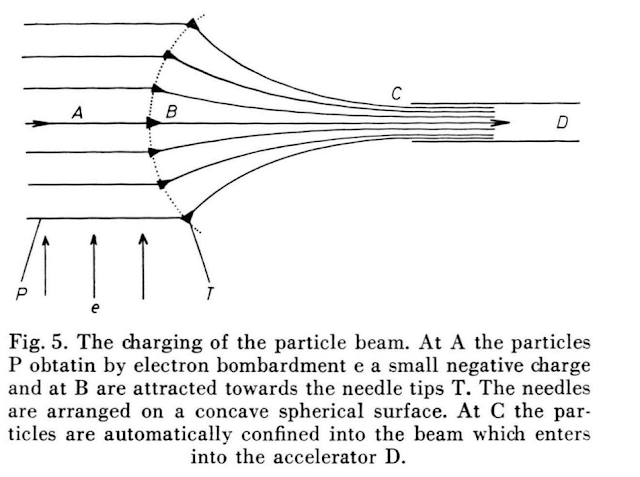 The total charge is given by:
- Surface charge = 1.11*10^-10* Voltage Gradient * Radius^2
Surface charge is in Coulombs (C)The voltage gradient within the projectile is in V/m
Radius is in mThe 1.11*10^-10 coefficient is (4*pi*Permittivity of Vacuum)The charge divided by mass, or charge to mass ratio, for a sphere is:- Charge to mass ratio = 2.655 * 10^-11 * Vg/(Radius * Density)
Charge to mass ratio is in C/kg.Vg is the voltage gradient within the projectile in V/m
Radius is in meters.
Density is in kg/m^3.These equations show that want to maximize the charge to mass ratio, the radius has to be very small and the voltage gradient as high as possible. The maximum voltage gradient for a negatively charged particle is about 100 MV/m. For a positively charged particle, this increases to 1,000 MV/m. Other sources mention voltage gradients as high as 50,000 MV/m as being possible, but that is likely to be a theoretical limit. If the particle is charged too much, it will start releasing electrons through field emission and dissipating the excess potential charge. For tiny projectiles, this causes enough heat to destroy them.We can suppose that any macron that we need to accelerate to very high velocities will be pushed to this limit.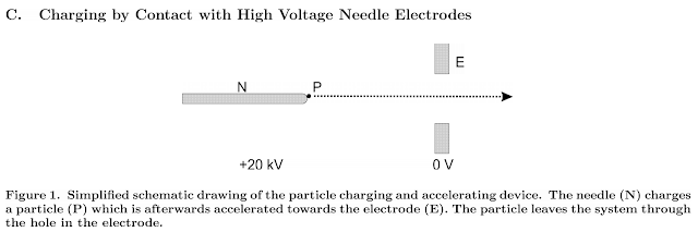 Let’s take the example of a positively charged 1 mm wide iron sphere. Radius is half of the diameter, so 0.5 mm or 5*10^-4 meters. The density is 8600 kg/m^3. The maximum charge to mass ratio will be 0.006 C/kg.Now let’s work out the C/kg for a positively charged 1 micrometre lithium sphere. Radius is 0.5 micrometres. Density is 534kg/m^3. The maximum charge to mass ratio for this macron is 99 C/kg.The lithium macron is clearly superior to the iron particle, because it is much smaller and composed of a less dense material.
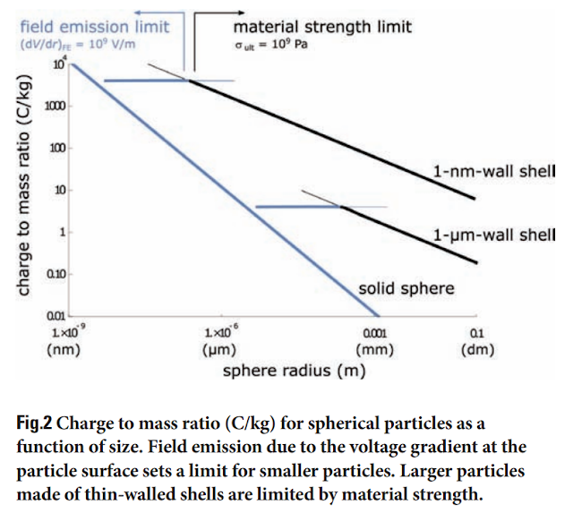 Another maximum is the strength of the macron’s materials. The voltage gradient creates a force that tensile strength must overcome. The equation for a macron stressed to the limits of its tensile strength is:
- Strength-limited C/kg = (1.77 * 10^-11 * T)^0.5/(R * Density)
The charge to mass ratio is in C/kg.T is the tensile strength in Pascals.
R is the radius in meters.
Density is in kg/m^3.Using the previous examples, a 1mm iron sphere with a strength of 250 MPa could survive a charge to mass ratio of 0.015 C/kg. This is a quarter of the previous limit.Lithium is rather weak with 15 MPa of tensile strength. A micrometre wide particle of lithium would only survive a charge to mass ratio of 0.99 C/kg, so it is strength limited to a hundredth of the previous value.To achieve better C/kg, we need stronger materials. The tiny dimensions of macrons bring forward another advantage to help meet this requirement. At a very small scale, we can expect materials to be formed without any defects. This unlocks their full strength potential.A good example of this small-scale advantage is iron.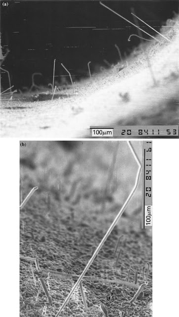 Bulk iron has a strength of 250 MPa. However, a micrometre-long monocrystalline whisker of iron displays strengths of 14,000 MPa. The charge to mass ratio allowed by micro-scale iron’s strength is 0.12 C/kg.This difference in strength between bulk and micro-materials can be demonstrated for graphite, aluminium, silicon and many others.A silicon nitride whisker has a strength of 13,800 MPa and a density of 3200 kg/m^3. It can have a micro-scale charge to mass ratio of 309 C/kg.The current champions of strength to weight ratio are carbon fibres. The Toray T1100G fibre is the strongest material commercially available for its weight, at 7,000 MPa for 1,790 kg/m^3. A micrometre-sized sphere of these fibres can support charge to mass ratios up to 393 C/kg.
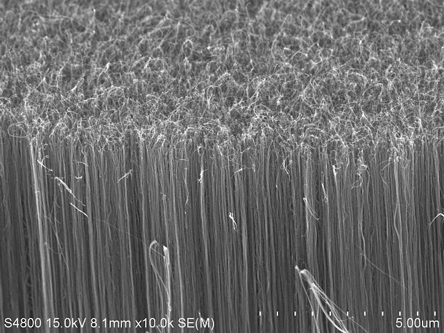 At the microscopic scale, those same carbon fibres gain the incredible properties of carbon nanotubes. They have shown strength to weight ratios more than ten times better than Toray T1100G fibres (about 63,000 MPa for 1340kg/m^3), which means charge to mass ratios of at least 1,576 C/kg at the same scale.How do we actually use the full potential of these small-scale materials if by making them stronger, we run again into the field emission limit on charge to mass ratio?Shaping the macronThe solution to more C/kg is to move past simple spheres.
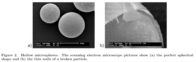 The spheres can be made hollow. This retains the surface area of a sphere but decreases the mass. We can call W the ratio of wall thickness to radius. W=0.5 means that the walls are half as thick as the sphere’s radius. W=0.01 means that the walls are a hundred times thinner than the sphere’s radius.The wall thickness ratio can by multiplied against the density in the previous equations to give the field-emission-limited charge to mass ratio of a hollow shell:
- Hollow C/kg = 0.02655 / (Radius * W * Density)
The charge to mass ratio is in C/kg.R is the radius in meters.
W is the wall thickness ratio.
Density is in kg/m^3.
This limit improves by a factor 1/W as the wall to thickness ratio decreases. At W:0.1, the field-emission-limited C/kg is increased by a factor 10. At W:0.01, it is a hundred-fold better.However, a hollow shell has W times less thickness to resist forces, and also has W times less mass to support. The strength-limited charge to mass ratio becomes:- Hollow C/kg = (1.77 * 10^-11 * T * W)^0.5/(Radius * Density * W)
The charge to mass ratio is in C/kg.T is the tensile strength in Pascals.Notice how this limit improves by a factor 1/W^0.5 as the wall to thickness ratio decreases. The benefit from W:0.1 is only 3.3x, and from W:0.01 is 10x better than a full-thickness sphere.
W is the wall thickness ratio.
R is the radius in meters.
Density is in kg/m^3.
These equations for hollow spheres imply that as the walls get thinner, the strength of the projectiles becomes more important.There is also the option to shape the macron into a cylinder.Cylinders can be elongated to large length to width ratios, like in this paper. This gives them a better surface area to volume ratio than spheres. The ratio between the lateral surface area of a tube of elongation G and a sphere of equal volume is:
- Surface area ratio for cylinder vs sphere = 0.605*G^0.333
G is cylinder length divided by cylinder radiusA tube that is 1000 times longer than it is wide (G:2000), for example 1 um wide and 1 mm long, would have a surface area that is 7.6 times greater than a sphere of equal volume. Carbon nanotubes that are a few nanometres wide and up to several centimetres long would have G:10,000,000, so they are a 131 times better shape than a sphere.Cylinders, of course, can be hollowed out to become tubes. The benefits of elongation and wall thickness ratio are multiplied in this case.Ion beam for macron accelerationAn electrostatic accelerator can be used in an entirely different way to get a macron up to high velocities.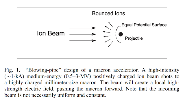 Instead of directly pushing and pulling on a macron using electric fields, it can act on it indirectly with a beam of electrons or protons. This has been called a ‘beam pushrod’ or a ‘beam blowpipe’.The charged surface of a macron naturally repels objects of similar charge. If it has an internal voltage gradient of 1000 MV/m and a diameter of 1 millimetre, it can repel particles with an energy of up to 500 keV. A thousand times smaller particle can only deflect particles of up to 500 eV, but it will accelerate harder thanks to the square-cube law. A negatively charged macron would only produce internal voltage gradients of 100 MV/m, so it would be deflecting 50 keV beams at 1mm and 50 eV at 1 um.
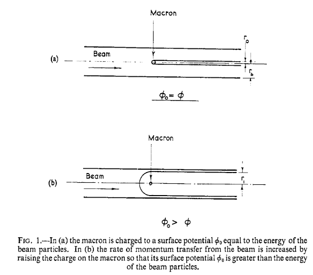 Less energetic beams can be deflected further away from the particle, giving it a larger effective cross-section. For example, a macron that could deflect a maximum of 50 eV electrons would be able to deflect 25 eV with an effective cross-section twice its actual physical size. We will assume that electric or magnetic fields are used to focus the charged beam onto a spot equal to the size of the macron’s effective cross-section throughout the length of the accelerator, as has been proposed here. Low energy charged beams will tend to expand very rapidly once outside the focusing influence of these lenses, so acceleration past the last focusing element can be ignored.The maximum acceleration that a macron can survive in these conditions is dependent on tensile strength:
- Maximum acceleration = (0.75 * T) / (R * Density)
Maximum acceleration is in m/s^2.T is tensile strength is in Pascals.
R is macron radius in meters.
Density is in kg/m^3.The value is independent of the wall thickness ratio.A millimetre-sized projectile made of a material such as aluminium 7075-T651 (570 MPa, 2800 kg/m^3) could be accelerated at up to 1.52*10^8 m/s^2.Meanwhile, a micrometre-sized sphere of diamond (1600 MPa, 3510 kg/m^3) would accelerate at 3.42*10^11 m/s^2.To accelerate a positively charged macron, a proton beam would be used. At 500 keV, protons have a velocity of 9,780 km/s. At 500 eV, this falls to 300 km/s.A negatively charged macron can be pushed by an electron beam. Electrons with an energy of 50 keV travel at 123,000 km/s. At 50 eV, it is 4190 km/s.These figures do not mean that the macron can only asymptotically approach the beam’s own velocity. They are the maximum relative velocity between the beam and the macron. If the macron is already travelling at 4190 km/s (50 eV electrons), then it can actually deflect 100 eV electrons (5929 km/s). A series of pulses from a particle accelerator, each tuned to have an energy that closely matches that of a macron, can bring that macron up to higher and higher velocities in steps. This is also good for transferring momentum to the macrons efficiently.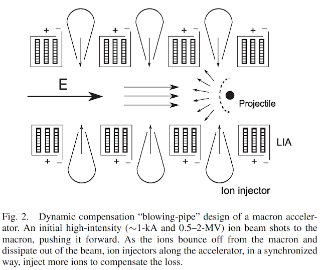 Pushing a macron with a charged beam has the advantage that almost any beam intensity can be used. Since the protons or electrons do not touch the macron and are instead deflected electrostatically, none of their energy is converted into heat. Also, the accelerating tube can be equipped with electrostatic or electromagnet lenses that can focus a charged beam and maintain high intensity throughout the duration of the acceleration. The beam energies are relatively low, so the focusing elements can be very lightweight and the acceleration tube extended without great mass penalties.Other than the strength of the macrons, the limit on ‘pushrod’ acceleration is the beam’s charge density.
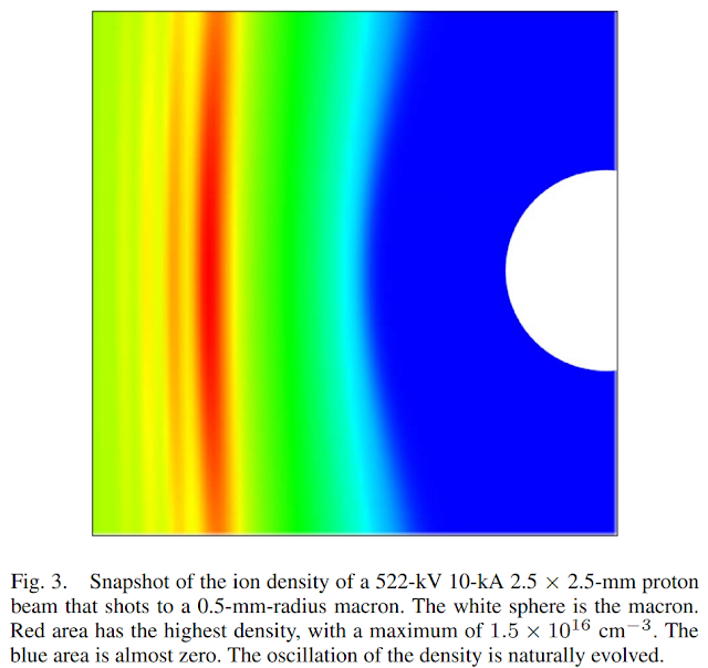 Protons or electrons do not like being bunched up behind a macron. They repel each other. If we can only put a certain number of charged particles behind a macron (the current density), we can only deliver so much energy, which limits acceleration.For a pulse of non-relativistic protons and electrons bouncing off a macron, the maximum current density is given by the Child-Langmuir Law:
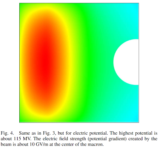
- Maximum Current Density = (7.7*10^6*BE^1.5*R)/(Pulse Duration* BV)
Current density is in Amperes per square meter (A/m^2)BE is beam energy in electronvolts (eV)
R is macron radius in meters
Pulse Duration is in seconds
BV is Beam Velocity in meters per second.For a 500 keV beam of protons composed of 1 nanosecond pulses, pushing on a micrometre-sized particle, we have BE: 500,000 eV, radius 0.5*10^-6 meters, pulse duration 10^-9 seconds and BV is 9,782,000 m/s. The maximum current density becomes 1.39*10^12 A/m^2.For a 50 eV beam of electrons composed of 1 microsecond pulses, pushing on a millimetre-sized particle, we have BE: 50 eV, radius 0.5*10^-3 meters, pulse duration 10^-6 seconds and BV is 4,193,200 m/s. Maximum current density becomes 3.24*10^6 A/m^2.To maximize intensity, and therefore acceleration, we want the shortest pulses of the highest energy protons.We can simplify the process for finding out the acceleration of a spherical macron by working with the power delivered by the pulses:- PA = ((0.375 * Current Density * BE)/(R * Density * PD * W))^0.5
PA is Pulse Acceleration in m/s^2.Current density is in A/m^2.
BE is beam energy in eV.
R is macron radius in meters.
Density is in m^2
PD is Pulse duration in seconds.
W is the wall thickness ratio.Following on from the previous examples:A 500 keV beam pushing a micrometre-sized particle made of diamond (3510 kg/m^3) with nanosecond pulses of protons would provide an acceleration of 3.85 * 10^15 m/s^2. This is a value greater than the maximum the hollowed-out diamond macron could survive mechanically, as calculated above.A 50 eV electron beam pushing on a sphere of aluminium a millimetre wide achieves an acceleration of 1.75*10^7 m/s^2. This is lower than the maximum the macron can handle. The macron’s shape could also be improved for use in this type of accelerator. A flat disk catches a larger beam, and so more energy could be transferred with each pulse. A web of fibres, inspired by the designs for electric sails, could have exceedingly high beam capture areas for their mass.
 Producing the beam that pushes the macrons is generally not a challenge. Low energy electron beam specifically can be very lightweight, efficient and small. If we base ourselves on the designs of inductive output tubes, 15 kW/kg at over 80% efficiency is to be expected from today’s technology. Proton beams are trickier to produce, but they will still be small and lightweight in absolute terms. Their energy will come from the same RF generators as mentioned previously. See the Particle Beams in Space post for more details.Since only one particle can be accelerated in a ‘pushrod’ accelerator at a time, it would make sense to also have those generators feed a multitude of accelerator tubes in sequence. 10 generators, each capable of producing 1 GHz of nanosecond pulses, could feed 10 tubes with a continuous supply of pulses each; if each macron clears a tube in 0.1 milliseconds, then ten tubes would have a maximal firing rate of 100,000 projectiles per second.
 This might seem like a lot, but each projectile is expected to carry very little energy. A nanogram at 1000 km/s is still only 0.5 joules. A hundred thousand of them per second is just 50 kW. Accelerators in the megawatt range would end up looking like a volley gun or a ‘Metal Storm’ launcher.HypervelocitiesHere is a selection of macrons to represent the different approaches to maximizing their performance
 1) A 1 mm diameter sphere of diamond with 1,600 MPa strength and 3510 kg/m^3 density. It is hollowed out to a 1:1000 wall to radius thickness ratio (W:0.001). It masses 1.83*10^-9 kg. When charged negatively, it can support a charge to mass ratio of 1.5 C/kg. Charged positively, it achieves 3 C/kg. 50 keV electrons and 500 keV protons can be deflected. Maximum acceleration is 6.8*10^11 m/s^2.2) A micrometre-sized macron made up of carbon fibres with 7000 MPa strength and 1790 kg/m^3 density. It is hollowed out to a 1:100 wall to radius thickness ratio (W:0.01). It masses 9.4*10^-16 kg. When charged negatively, it can support a charge to mass ratio of 296 C/kg. Charged positively, it achieves 2960 C/kg. 50 eV electrons and 500 eV protons can be deflected. Maximum acceleration is 5.8*10^12 m/s^2.3) A micrometre-wide, centimetre-long needle of carbon nanotubes with 63,000 MPa strength and 1000 kg/m^3. Wall to thickness ratio is 1:10 (W:0.01). It masses 7.8*10^-14 kg. When charged negatively, it can support a charge to mass ratio of 356 C/kg. With a positive charge, this becomes 3560 C/kg. 50 eV electrons and 500 eV protons can be deflected. Maximum acceleration (vertical axis) is 9.45*10^13 m/s^2.4) A 10 nanometre diameter sphere of carbon nanolattice with 200 MPa strength and 300 kg/m^3 density. It masses 1.6*10^-22 kg. When charged negatively, it can support a charge to mass ratio of 8850 C/kg. Charged positively, it achieves 39,665 C/kg. 0.5 eV electrons and 5 eV protons can be deflected. Maximum acceleration is 1*10^11 m/s^2.We select the maximal value for C/kg depending on the accelerator type. All of these particles are field-emission-limited so they could be further optimized to match their strength-limited C/kg values.The accelerators we will look at are:
A) A single-stage 10 MV electrostatic accelerator.
B) A 100m long multi-stage electrostatic accelerator with an average acceleration gradient of 3 MV/m, for a final energy of 300 MV.
C) A 100m diameter ring of 10 Tesla field strength.
D) A 100m long electron ‘pushrod’ accelerator.
E) A 100m long proton ‘pushrod’ accelerator.Their performance is as follows:A1) 7.7 km/sA2) 243 km/sA3) 266 km/sA4) 890 km/sB1) 42 km/sB2) 1,332 km/sB3) 1,461 km/sB4) 4,877 km/sC1) 1.5 km/s
C2) 1,480 km/sC3) 1,780 km/sC4) 19,827 km/sD1) 11,661 km/s
D2) 721 km/sD3) Cannot.
D4) 35.7 km/s
E1) 11,661 km/s
E2) 10,392 km/s
E3) Cannot.E4) 913 km/sSome conclusions can be drawn from these values.Larger macrons are limited mainly by their strength. The identical D1 and E1 values are because the acceleration reaches the maximum the thin-shelled diamond sphere can handle in the ‘blowpipe’ accelerator.For the smallest macrons, where C/kg is large, circular accelerators become more interesting than linear accelerators (at least if we are not concerned about the weight of the magnets). We can see the progression of velocities from C1 to C4 being much more pronounced than from B1 to B4.Also of note is the fact that fibre tubes excel in electrostatic accelerators, but cannot be pushed by a ‘blowpipe’ accelerator as they would bend under those stresses.Fission EnhancementMillimetre-sized macrons have an interesting property. They can hold a ‘payload’ of a few milligrams within their hollow core. If they are filled with a fissile material, they can bring it up to sufficient velocities to ignite a nuclear reaction upon impact.Studies for ignition of ‘micro-fission’ have been conducted by researchers such as Winterberg. They worked out that a 0.2 milligram projectile of uranium-235, when covered in a shell of deuterium/tritium ice, could ignite when compressed to about 10*10^12 Pa. In response to those calculations, another study was performed where the critical mass of uranium enclosed deuterium/tritium (DT) ice was calculated. It then goes on to describe methods of igniting micro-fission by the impact of hypervelocity projectiles. At 20 km/s, the critical mass is just 0.04 grams.This mass of uranium would fit inside a sphere of 1.6 mm in diameter. Surrounded by a shell of DT ice of equal thickness, and then a 10 micrometer thick shell of carbon fibre, it would have a total diameter of 3.18 mm and a mass of 0.0422 grams. Average density is 2502 kg/m^3 and the C/kg value when positively charged is 0.0067 C/kg.At an average voltage gradient of 3 MV/m, a linear electrostatic accelerator would have to be 9.9 km long to push this macron to the required 20 km/s velocity. 10 tesla strength magnets would give it a bend radius of 298.5 km. These are impractical options.With the shell of carbon fibre handling mechanical stresses, an acceleration of 8.29*10^6 m/s^2 is possible. This means a velocity of 20 km/s is achievable within an accelerator length of 24 meters. About 8.44kJ of energy is consumed in 2.4 milliseconds.Upon impact, the uranium releases a large portion of its 80 TJ/kg nuclear energy. With 100% burnup, this amounts to a kinetic-to-nuclear energy multiplier of 379,149! Even at a low 10%, this is 37,915 times the energy invested.A 1 MW accelerator shooting nearly 120 of these micro-fission macrons per second would produce between 38 and 380 GW of power at the target.The paper also suggests a scaling law where increasing the impact velocity reduces the critical mass by a factor Velocity^12/5.An impact at 200 km/s could be enough to reduce the critical mass to 0.16 milligrams. This quantity of uranium fits inside a spherical volume that is 0.252 mm wide.Adding the required layer of deuterium/tritium ice brings the diameter to 0.5 mm and the mass to 0.161 milligrams.
 This tiny fuel particle can be comfortably help inside the 1mm diameter diamond shell described earlier as projectile 1. The mass of the macron would increase from 0.00183 milligrams empty to 0.162 milligrams loaded. Its C/kg value and maximum acceleration would fall by a factor 89. An electrostatic accelerator with an average voltage gradient of 3 MV/m would have to be 197.8 km long. A 10 Tesla ring of magnets would have to be 1,186 km in diameter. These are again clearly not wise choices.In a ‘blowpipe’ type accelerator, an acceleration reduced by a factor 89 still permits a velocity of 200km/s to be achieved within a mere 2.2 meters of length.The advantage of a smaller, faster micro-fission macron is that it can reach targets further away in less time. However, the energy multiplication effect is greatly reduced.A 200 km/s projectile contains 20 GJ/kg of kinetic energy. Nuclear fission releases only 4x this amount. If we factor in incomplete burn-up of the fuel, it is likely that there won’t be a significant increase in the energy delivered.Impact FusionGreater macron velocities can focus more energy into an impact. These impacts generate incredible temperatures and pressures… conditions under which deuterium-tritium fuel with undergo thermonuclear ignition.
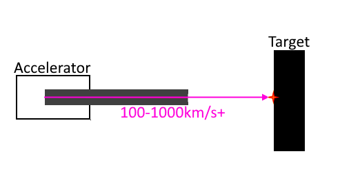 Winterberg once again leads the way in providing the theory and maths behind these exciting high energy physics applications. He states that a macron accelerated to over 100 km/s can generate temperatures of over 300 million K and compress fusion fuel to a density of 1000 kg/m^3 (10x that of DT ice).
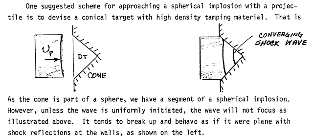 Another source mentions 100 km/s ignition being possible only if the fuel is surrounded by a collapsing shell of material, and 50 km/s might only needed if the impactor is shaped into a conical shape.
Igniting fusion using hypervelocity impacts has several major advantages.There is no minimum ‘critical mass’ of fuel, so the smallest macrons can be used. The confinement and fuel burn time depends on the length of the projectile divided by the velocity. This favours elongated fibres with a tip of fuel; also a great shape for achieving 100 km/s with accelerators of reasonable length.
Another source mentions 100 km/s ignition being possible only if the fuel is surrounded by a collapsing shell of material, and 50 km/s might only needed if the impactor is shaped into a conical shape.
Igniting fusion using hypervelocity impacts has several major advantages.There is no minimum ‘critical mass’ of fuel, so the smallest macrons can be used. The confinement and fuel burn time depends on the length of the projectile divided by the velocity. This favours elongated fibres with a tip of fuel; also a great shape for achieving 100 km/s with accelerators of reasonable length.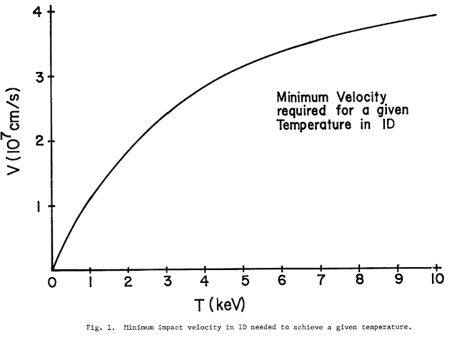 DT fuel contains about 330 TJ/kg of energy, meaning that there is an energy multiplication effect of 66,000 at 100 km/s (assuming 100% burnup) and the energy gain can be maintained at up to 25,690 km/s!
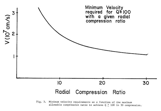 This is an important fact, as many sources mention ignition velocities instead of at least a few thousand km/s.We could, for example, fill the millimetre-sized diamond shell described above as projectile 1 with DT ice. It would be able to hold 78 micrograms of fuel, which is 43.8 times the shell’s own mass. The macron’s maximum acceleration is reduced by this extra load, but it still manages to reach 100 km/s in a ‘blowpipe’ accelerator of just 31 cm.A 1 MW accelerator would be firing off 2,500 of these projectiles per second. Up to 64 GW of fusion energy could then be released at the target.PropulsionThe smallest, lightest macrons can be accelerated to velocities exceeding 10,000 km/s. This translates to an Isp of 1,000,000 seconds. Only the most powerful electric engines or advanced propulsion system are capable of this. In the future, fusion energy can exceed this exhaust velocity.A hypervelocity macron is an improvement over other types of propulsion that achieve those Isps in that it can be shaped out of any sort of common dust, and does not need to emit radioactive material. The energy source could be solar or a closed-cycle nuclear reactor. Kinetic streams of projectiles have been thoroughly discussed as an efficient propulsion system, even up to interstellar velocities.
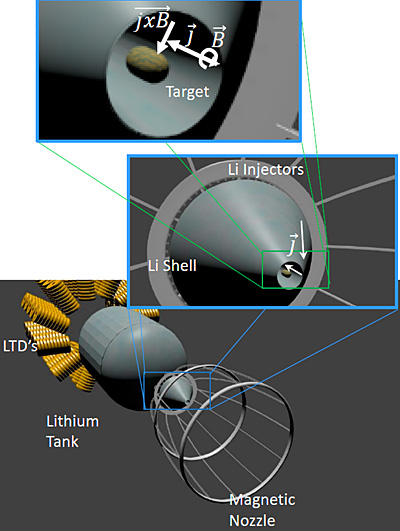 Fission enhanced macron projectiles are particularly suited for use as a propulsion system. Lower impact velocity requirements means less drive mass, while the ability to greatly reduce the critical amount of uranium also means a great reduction in the minimum pulse energy. Project Orion, for example, assumed a minimum release of 627 gigajoules with each nuclear pulse; any lower and the uranium fuel would be wasted in incomplete burns. Mag-Orion, a Z-pinched variant with a magnetic nozzle, managed 340 GJ thanks to the use of expensive Curium-245. A macron accelerator with 0.04 grams of uranium would only release 3.2 GJ, a hundred times less.This reduction in pulse energy means smaller suspension, smaller magnetic nozzles or thrust plates, reduced heat loads and smoother accelerations. Less equipment has to be dedicated to recovering and storing energy in between pulses. Maneuvers can be done more precisely. There is much less risk of damage in case of a misfire.
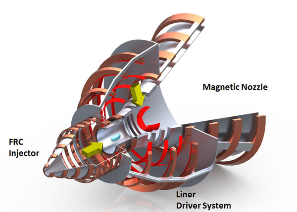 A fusion rocket that uses macron propulsion enjoys many of these advantages too. A kinetic impactor can concentrate the output of an ignition mechanism like an ion beam from a particle accelerator from several milliseconds to less than a nanosecond. The exceedingly difficult peak power needed to ignite fusion is therefore replaced by a thousand to a million times less demanding accelerator. The ignition event can also feasibly be made to take place far away from the engine’s physical structures too. Macrons retain their velocity while drifting through space, so they are just as capable of igniting fusion a hundred meters from a spaceship as a meter away; this is especially important if drive powers on the order of terawatts are needed for a ‘torch drive’.But these are minor gains compared to the possibility of remotely-accelerated macron-driven propulsion systems.A stream of macrons can be accelerated a long distance away from a spaceship. They can cross large distances relatively quickly, and then deliver their kinetic energy without any losses. Multiple macrons be fired with a small velocity difference so that over time they bunch together and all simultaneously, providing much higher peak power. All the receiving ship has to do is place an obstacle into the path of the macrons so that the impact creates a plasma explosion. This plasma can be redirected by a magnetic nozzle for thrust. At 100 km/s, the energy needed to vaporize a carbon macron is about 83 times lower than the kinetic energy is contains, so we can expect 1 kg of onboard obstacle material to vaporize 83 kg of incoming carbon macrons.This sort of propulsion system is similar to beamed propulsion concepts. Propulsive power is delivered without the need for heavy on-board reactors, so high accelerations are possible. The ratio of obstacle material to macron stream mass means that the effective Isp of propellant onboard the spaceship is greatly multiplied too.Compared to other mass-stream designs for propulsion, each macron carries a tiny amount of energy. It is unlikely that they will do significant damage if a few of them do not hit the intended target.There is also the possibility to have fission or fusion-enhanced macrons act as propellant for a spaceship. Now we can have small accelerators delivering huge amount of propulsive energy to lightweight spacecraft, to achieve great accelerations and impressive levels of deltaV.
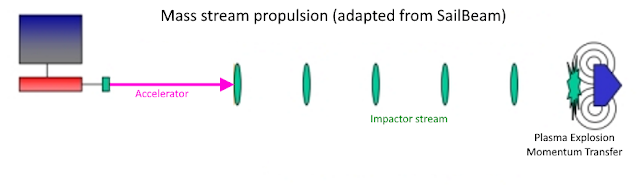 For example, a fission-enhanced stream of macrons could produce a series of nuclear detonations by impacting an obstacle placed inside a magnetic nozzle. The exhaust would be fission fragments with a velocity of 10,000 km/s. A stream of 10 kg/s would release perhaps 80 TW of power. If it takes 1 kg of obstacle material to receive 100 kg of macrons, then a 1000 ton craft with 200 tons of obstacle material would accelerate on average at 1.81g and achieve a total deltaV of 35.7 thousand km/s.In other words, a 50 GW accelerator can do the work of an 80 TW drive and reduce trip times from Earth to Jupiter to 9.8-14.5 hours for 1000 ton spacecraft.A laser or particle beam can be used to vaporize incoming macrons. This removes the need for onboard obstacle material to serve as propellant (so deltaV becomes unlimited), but also destroys the structures needed for fission or fusion enhancement, so the energy multiplication effect is also lost.Those lasers or particle beams can also be used to ‘guide’ the macrons down a specific path. The beams can effectively create an electrical field gradient that holds the macrons in the beam’s centre, or can even be bent by uneven gradients. More details in the Cold Laser-Coupled Particle Beams post.WeaponryAnother application for hypervelocity projectiles is as weapons.We have discussed the need for faster projectiles to compensate for the combat ranges imposed by powerful lasers. The ‘solution’ to this need was described as a ‘pellet’ or ‘dust’ gun. Its features accurately describe the properties of a macron accelerator.At first glance, a macron accelerator produces less watts of output for the same mass of equipment when compared to a laser or a particle beam accelerator. It might also be very bulky as it has many hollow spaces. Worst of all, it does not deliver its energy at or near lightspeed.A deeper look reveals its advantages.The macrons have a chance to hit determined by:
- Chance to hit = (TR/(0.5*TA * (Distance/MV)^2))^2
Chance to hit is a fraction.TR is the target’s radius in metres.TA is the target’s acceleration in m/s^2Distance is the distance to cross in meters.MV is the velocity of the macron in m/s.The chance to hit equation basically compared the cross-section of the target to the area the target could potentially cover in the time it takes for a projectile to arrive.We can see that a 1000 km/s macron targeting a 5 meter radius spaceship that accelerates at 0.5 g (4.5 m/s^2) from a distance of 2,000 km will hit about 30% of the time.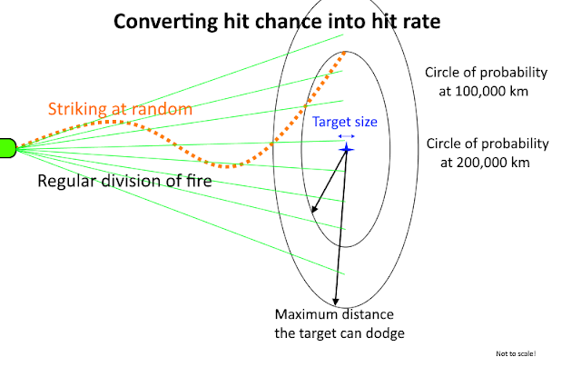 The equation can be rearranged to determine the effective range of a macron for a certain hit chance:
- Effective range = MV * TR^0.5 / (Chance to hit^0.25 * (0.5 * TA)^0.5))
Effective range is in meters.M is the velocity of the macron in m/s.TR is the target’s radius in metres.Chance to hit is a fraction.TA is the target’s acceleration in m/s^2If we accept a chance to hit of 10% with a 1000 km/s macron, a 5 meter radius target accelerating at 0.5 g can be engaged at a distance of 2650 km. Note how the range is directly proportional to the macron’s velocity and that increasing acceleration has a much lower effect. Quadrupling the acceleration cuts the target’s deltaV by a factor 4 but only increases the range by a factor 2. This would have to be compensated for by exponentially more propellant.At the upper end of macron velocities, we can expect effective ranges in the hundreds of thousands of kilometres with good hit chances.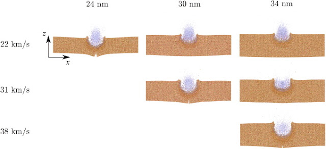 The projectiles deliver their kinetic energy as small plasma explosions that form craters in a target’s armor. An approximation suggested by Luke Campbell is that a hypervelocity impactor excavate a volume of material equal to the kinetic energy divided by three times the yield strength of that material. For something relatively weak, like graphite, this means that the kinetic energy is divided by 2.4*10^8 J/m^3. Vaporizing graphite requires about 500 times more energy per m^3; in other words, a macron accelerator can be 500 times more efficient at removing armor than a continuous beamed weapon, and even better than a pulsed laser.Stronger materials like carbon fibres require only 5 times more energy to vaporize than to excavate, but this is a still major boost to the destructive efficiency of kinetic weapons.We can expect a 100 MW stream of macrons impacting hypervelocity to excavate about 0.41 m^3 of graphite or 0.03 m^3 of carbon fibres per second. Using a 100x nuclear energy multiplier upon impact, these volumes can be multiplied to 40 and 3 m^3/s. The actual penetration rate through armor depends on the spacing of the impacts. Closely space impacts, such as within a spot 1 meter wide, would mean a penetration rate of 50.9 m/s through graphite! A wildly maneuvering target might have this potential damage spread out over their entire cross section and then reduced further by the hit chance. Using previous numbers, a 5 meter radius target with a 10% hit chance would find its exposed surfaces ablated at a rate of 5 cm/s if protected by graphite, and 0.38 cm/s using carbon fibres.
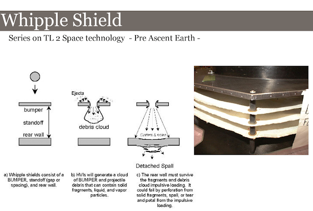 Whipple shields could be used to defend against kinetic projectiles. As mentioned in the Propulsion section, very little material is required to destroy an incoming macron. However, the gap created in a whipple shield by the impact of one macron can let through thousands more unimpeded.
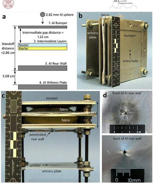 It is much harder to add one more layer of shielding material than to fire one more macron to get through it…The macron accelerator’s offensive performance is also improved by fission or fusion enhancement. It is the only weapon system described so far that output more energy at the target than originally spent. A 1 MW macron accelerator might heavier and bulkier than a 1 MW laser or particle beam, but its actual output can be multiplied a hundred to a thousand times at the target. However much worse the macron accelerator is in a direct comparison, it is more than made up for by the addition of nuclear energy.To top this all off, macrons are expected to be completely undetectable until they hit their target. Their small size means that they cool down very quickly to temperatures hard to distinguish from background radiation. At the smallest scales (sub-micrometers), even LIDAR cannot interact with them properly, and even if specialized short-wavelength sensors are used, the resolution would be severely limited. If the detection and targeting problems are somehow overcome, the macrons are difficult to destroy en-route. Defensive lasers have very little time to act (seconds at most) and must face the fact that the surface area to mass ratio of the macrons makes them very good at radiating away heat.For example, a micrometre-sized sphere of carbon fibres could survive a beam intensity of 58 MW/m^2. A micrometre-wide, centimetre-long carbon needle survives 579 GW/m^2. We can therefore expect macrons shaped to handle high laser intensities to defeat even the most power defences (although DT ice is unlikely to remain solid!).
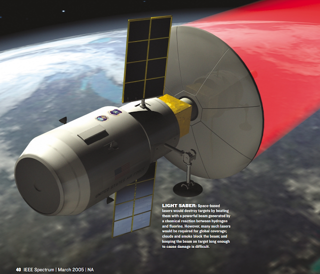 SDI-era research has been done on macron accelerators for space defense. It is now up to you to decide how to make use of hypervelocity macrons.Thanks for the help of GerritB, Kerr and other ToughSF members for help with researching this topic.
 -
@DDEThere is a scene in the show where a character (Amos) takes a bumpy ride in the space between external and internal hulls. Also, the projectiles hitting spaceships like the Donnager or the Rocinante go through the walls with minimal resistance or shrapnelling, suggesting they are very thin walls.
-
On 10/7/2019 at 6:57 PM, sevenperforce said:
Ah, good point. That could prove problematic. If you want to burn radial, great, but if not then you're going to have a great deal of trouble "collecting" all that hydrogen.
Of course, relative to 8.9% c, 700 km/s might as well be standing still.
The spaceship itself will only be travelling a maximum of 2000km/s
-
1 hour ago, sevenperforce said:
At 30 km/s relative to Sol (at least near Terra), your magnetic ramscoop need only be 68,326,751 km in diameter...a little more than the diameter of Uranus.
The solar wind varies between 400 and 700km/s naturally.
-
20 hours ago, Scotius said:
Yes. And somehow it's still able to accelerate at 12 g's. And do combat maneuvers. Without crumpling like toilet paper under the force. It's good sci-fi, but propped up by pure handwaving and unobtanium-reinforced bovine metabolic waste products.
1cm thick walls in each 'room' would have a strength of 200MPa and handle about 680 tons at 12g.
Smaller rooms with more walls would handle even more weight, but be a bit denser.
-
1 hour ago, Scotius said:
Uh, you misunderstood me. I have nothing against styrofoam. Or spaceship insulation material. My post pointed towards ridiculous size-to-weight ratios of some imaginary spaceships, leading to them having absurdly low densities when someone math-savvy decides to bite the bullet and runs the calculations. From the OP:
"Using the battleship’s dimensions, we obtain an average density of about 20 to 40 kg/m^3. For comparison, the ISS has a density of 458 kg/m^3."
Do you see the problem?
Apparently spaceships in "Expanse" are like bouncy castles: outer shell filled by nearly nothing.
And said battleship necessarily needs to have things ISS lacks. Like massive engine, fuel plumbing, weapons, sturdy internal structure able to withstand accelerations Epstein Drive allows, maybe some armor etc.
*sigh*
It's not even the worst offender. Someone calculated densities of Weber's "Honorverse" warships, using official sizes and masses provided by the author. He concluded that said warships would have to be made out of cigarette smoke.
A 10x10x10m long volume with walls made of 1cm thick, 2000kg/m^3 composites, would have an average density of 12kg/m^3. The Rocinante is mostly a series of empty rooms and thin walls.
-
11 hours ago, mikegarrison said:
I believe the more simple and correct explanation is "it was necessary for the plot".
That's the easy way out!
9 hours ago, mikegarrison said:Well, it's just that this is the science forum, not the science fiction forum.
Only science was used in the blog post, and you can replace the 'Epstein Drive' name with 'Generic powerful fusion engine'.
6 hours ago, Scotius said:Eh, i can deal with crazy effective propulsion. Modern internal combustion engines came a very long way from the first steam engine, after all. What i find difficult to accept, are spaceships made out of styrofoam. "Science fiction writers have no sense of scale" - indeed
")
That's why I felt that I had to add a Scaling section to the post, to account for people who have different ideas of how much the Rocinante should mass.
-
This is a blog post from: http://toughsf.blogspot.com/2019/10/the-expanses-epstein-drive.html
The Expanse's Epstein Drive
We aim to take a fictional propulsion technology from The Expanse, and apply the appropriate science to explain its features in a realistic manner.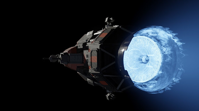 This also applies to other SciFi settings that want a similar engine for their own spacecraft.The Epstein Drive
 Title art is from here.Central to the setting of The Expanse is a very powerful fusion-powered engine that allows spacecraft to rocket from one end of the Solar System to the other quickly and cheaply.It reduces interplanetary trips to days or weeks, allows small shuttles to land and take off from large planets multiple times and accelerate at multiple g’s for extended amounts of time.Such a propulsion system is known as a ‘torch drive’: huge thrust, incredible exhaust velocity and immense power inside a small package.Fusion energy can certainly provide these capabilities. Using fuels like Deuterium provides over 90 TeraJoules of energy per kilogram consumed. Proton fusion, the sort which powers our Sun, could release 644 TJ/kg if we could ever get it to work.
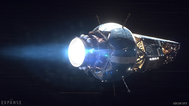 The Epstein Drive (art Gautam Singh) is described in The Expanse as a breakthrough in fusion propulsion technology. A short story provides some details. A small spaceship equipped with this engine could reach 5% of the speed of light in 37 hours, averaging over 11g’s of acceleration. A magnetic bottle is mentioned. Since we don’t know the mass of the vehicle or what percentage of it was propellant, we can’t work many useful details.The main book series and the TV show focus on the adventures of the Rocinante and its crew. We know that it uses laser-ignited fusion reactions and water as propellant. Again, we don’t have a mass or propellant fraction, so we cannot get definitive performance figures. However, we have detailed images of its interior and exterior. Note that there are no radiator fins or any heat management system visible.The cross-section also reveals that there is very little room for propellant. Despite this, it can accelerate at over 12g’s and has reached velocities of 1800km/s while averaging 5g. Presuming that it can slow down again and jet off to another destination, this implies a total deltaV on the order of 4000km/s, which is 1.33% of the speed of light.
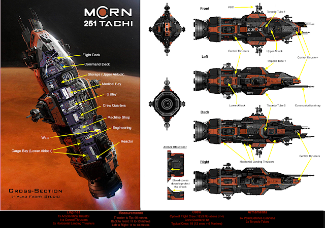 Official figures for the masses of spacecraft from The Expanse do exist. In collaboration with the TV show’s production team, SpaceDock created a series of videos featuring ships such as the Donnager-class Battleship for which a mass of 250,000 tons is provided.Using the battleship’s dimensions, we obtain an average density of about 20 to 40 kg/m^3. For comparison, the ISS has a density of 458 kg/m^3.
 Applying the battleship density to the Rocinante's size gives us a mass of about 130 to 260 tons. It is likely to change a lot depending on what the ship is loaded with, seeing as it is almost entirely made up of empty volumes. We’ll use a 250 tons figure for an empty Rocinante and add propellant to it as needed.Let’s put all these numbers together.
 The Epstein drive technology allows for >250 ton spacecraft to accelerate for several hours at 5g with bursts of up to 12g, achieving a deltaV of 4000km/s, while not having any radiators and a tiny propellant fraction.Can we design a realistic engine that can meet these requirements?The Heat Problem
 The biggest problem we face is heat.No engine is perfectly efficient. They generate waste heat. Some sources of waste heat are physically unavoidable, however performant the machinery becomes.Fusion reactions result in three types of energy: charged kinetic, neutral kinetic and electromagnetic.Charged kinetic energy is the energy of the charged particles released from a fusion reaction. For a proton-Boron reaction, it is the energy of the charged Helium ions (alpha particles) that come zipping out at 4.5% of the speed of light.
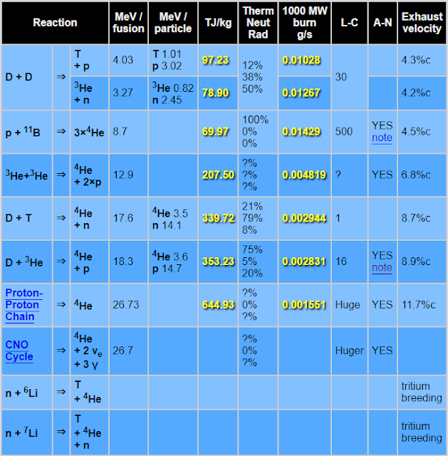 We want as much of the fusion reaction to end up in this form. Charged particles can be redirected out of a nozzle with magnetic fields, which produces thrust, or slowed down in a magnetohydrodynamic generator to produce electricity. With superconducting magnets, the process of handling and using charged kinetic energy can be made extremely efficient and generate practically no heat.Neutral kinetic energy is undesirable. It comes in the form of neutrons. For deuterium-tritium fusion, this represents 80% of the fusion output. We cannot handle these particles remotely as they have no charge, so we must use physical means. Neutron shields are the solution; the downside is that by absorbing neutrons they convert their all of their energy into heat. This is a problem because materials have maximum temperatures and we cannot really use radiator fins to remove the heat being absorbed.
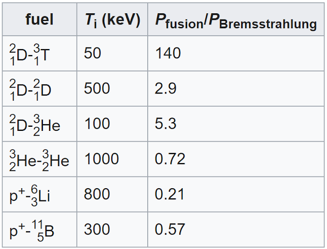 Electromagnetic radiation is another unavoidable source of heat. Mirrors can reflect a lot of infrared, visual and even ultraviolet wavelengths. However, fusion reactions happen at such a high temperature that the majority of the electromagnetic radiation is in the form of X-rays. These very short wavelengths cannot be reflected by any material, and so they must also be absorbed.With this information, we can add the following requirements:-We must maximize energy being released as charged particles.-We must minimize heat from neutral kinetic and electromagnetic energy.Thankfully, there is a fusion reaction that meets these requirements.
Helium-3 and Deuterium react to form charged Helium-4 and proton particles. Some neutrons are released by Deuterium-Deuterium side reactions, but by optimizing the reaction temperature, this can be reduced to 4% of the total output. An excess of Helium-3 compared to Deuterium helps reduce the portion of energy wasted as neutrons down to 1%. Another 16% of the fusion energy becomes X-rays. Other ‘cleaner’ source of fusion energy exists, using fuels such as Boron, but they cannot be ignited using a laser.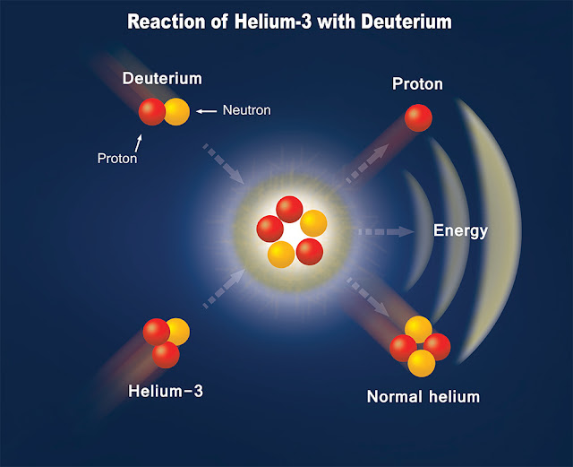
Diagram from here. An optimized Deuterium and Helium-3 reaction therefore releases 1 Watt of undesirable energy (which becomes waste heat if absorbed) for every 4 Watts of useful energy.If this reaction takes place inside a spaceship, then all of the undesirable energy must be turned into heat. However, if it is done outside the spaceship, then we can get away with only absorbing a fraction of them. It's the idea behind nuclear pulsed propulsion.How else do we reduce the potential heat a spaceship has to absorb?Distance.A fusion reaction produces a sphere of very hot plasma emitting neutrons and X-rays in all directions. A spaceship sitting near the reaction would eclipse most of these directions and end up absorbing up to half of all this undesirable output.If the fusion reaction takes place further away, less of the undesirable output reaches the spaceship and more of it escapes into space.It is therefore a good design choice to place the fusion reaction as far away as possible. However, we are limited by magnetic field strength.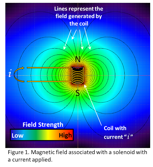 The useful portion of the fusion output, which is the kinetic energy of the charged particles, is handled by magnetic fields to turn it into thrust. Magnetic fields quickly lose strength with distance. In fact, any magnetic field is 8 times weaker if distance is merely doubled. 10 times further away means a field a 1000 times weaker. If we place the fusion reaction too far away from the source of these magnetic fields, then the useful fusion products cannot be converted into thrust.We could calculate exactly how far the fusion reaction could take place from the spaceship while still being handled by magnetic fields, but whether you use magnetic beta (magnetic pressure vs plasma pressure) or the ion gyroradius (turning radius for fusion products inside a magnetic field), it is clear that kilometres are possible with less than 1 Tesla. For a setting with the Expanse’s implied technology level, generating such field strengths is easy.What does this all mean for a fusion engine?If we can generate a magnetic field strong enough to deflect fusion particles at a considerable distance, then we can convert a large fraction of the fusion output into thrust while only a small fraction of harmful energies reaches the spaceship.
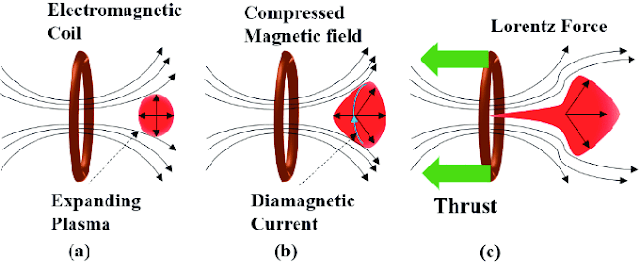 The Rocinante is about 12 meters wide. If we describe it as a square, it has a cross-section of about 144m^2. A fusion reaction taking place 20 meters away from the spaceship would have spread its undesirable energies (neutrons and X-rays) over a spherical surface area of 5027m^2 by the time they reach the Rocinante. This means that 144/5027= 2.86% of the fusion reaction’s energy is actually intercepted by the spaceship.Increase this distance to 200 meters and now only 0.0286% of the fusion reaction’s harmful output reaches the spaceship. A much more powerful fusion output is possible.Finally, we need a heatshield.
Despite only a portion of the fusion output being released as neutrons and X-rays, and a small fraction of even that becoming radiation that actually reaches the spaceship, it can be enough to generate melt the ship.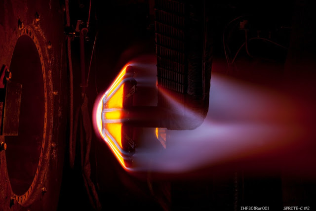
NASA heatshield materials test. We therefore need a final barrier between the fusion reaction and the rest of the spaceship. A heatshield is the solution.This heatshield needs to enter into a state where it balances incoming and outgoing energy. With no active cooling available, no heatsinks or external fins, the heatshield has to become its own radiator.The Stefan-Boltzmann law says that a surface can reach the state described above at its equilibrium temperature. It can be assumed that emissivity is high enough to not matter (over 0.9).Equilibrium temperature = (Incoming heat intensity/ (5.67e-8))^0.25Equilibrium temperature is in Kelvin.The heat intensity is in Watts per square meter (or W/m^2)Using this equation, we can work out that an object sitting under direct sunlight in space (at 1 AU from the Sun, so receiving 1361 W/m^2) would have an equilibrium temperature of 393 Kelvin.A concentrating mirror focusing sunlight to 1000x intensity (to 1.36 MW/m^2) would heat up an object to the point where radiates heat away at a temperature of 2213K.For a fusion-powered spaceship, you want this temperature to be as high as possible. Higher temperatures means that the incoming heat intensity can be greater, which in turn means that the spaceship can shield itself from more powerful fusion outputs.Tungsten, for example, can happily reach a temperature of 3200K and survive a beating from 5.95MW/m^2.Graphite can handle 3800K before it starts being eroded very quickly. That’s equivalent to 11.8MW/m^2.Tantalum Hafnium Carbide is the current record holder at 4150K. Keep it below its melting temperature at 4000K, and we would see it absorb 14.5MW/m^2. Scientists have also simulated materials which could reach over 4400K before they melt.This heatshield needs to rest on good insulation so that it doesn’t conduct heat into the spaceship. A design similar to the Parker Solar Probe’s heatshield mounting can be used. Low thermal conductivity mountings and low emissivity foil can reduce heat transfer to a trickle.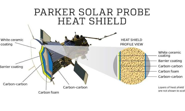 Proposed designLet’s talk specifics.We will describe now a fusion-powered rocket engine design that can perform most similarly to the Expanse’s Epstein Drive as shown on the Rocinante.
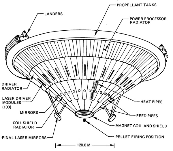 It is based on this refinement to the VISTA fusion propulsion design. Like the VISTA design, a laser is used to ignite a fusion fuel pellet at a certain distance from the ship and a magnetic coil redirects the fusion products into thrust. The rear face of the spaceship takes the full brunt of the unwanted energies and re-emits them as blackbody thermal radiation.
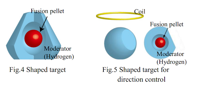 The refinement consists of a shaped fusion charge that can be ignited by laser slamming a portion of the fusion fuel at high velocity into a collapsing sphere, raising temperatures and pressures up to ignition levels.
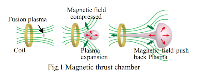 Instead of the fusion products being released in all directions, a jet of plasma is directed straight at the spaceship. This increases thrust efficiency up to 75%, as the paper cites.
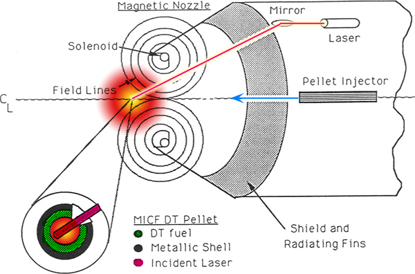
Somewhat similar magnetic nozzle configuration from this MICF design. Meanwhile, the X-rays and neutrons escape the plasma in all directions.The Epstein Drive is assumed to be a version of this. Instead of a spherical firing squad of lasers (as can be found in the NIF facility) that requires lasers to be redirected sideways with mirrors, a single laser is used for ignition. It is less effective but it means we can dispense with mirrors hanging in space.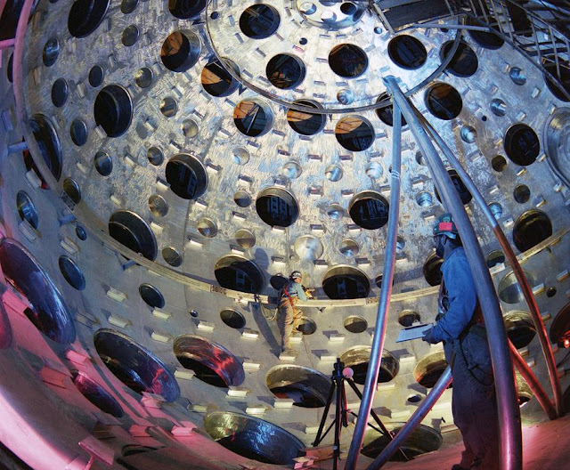
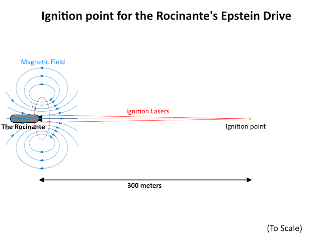 We will also be using Deuterium and Helium-3 fuels instead of Deuterium and Tritium. They are harder to ignite, but give much more useful energy (79% comes out as charged particles). By adjusting the fusion temperature and ratio of Helium-3 to Deuterium, we can increase this output to become 83% useful while neutrons fall to 1% of the output and X-rays represent 16%.Also, using powerful magnetic coils, we will be igniting the fusion pellets at a much greater distance from the physical structures of the engine. We can take the 'nozzle' to actually be a mounting for the magnetic coil and everything with a line of sight to the fusion reaction to be covered in a heatshield. More importantly, the engine will be much, much smaller than the 120m diameter of the VISTA design.The Rocinante has a cross-section area of 144m^2. Its heatshield will be a black metal carbide that can reach an equilbirium temperature of 4000K. It is separated from the hull with insulating brackets that massively reduce the heat being conducted to the 300K interior.
The heatshield needs to be thick enough to fully absorb X-rays and neutrons from the fusion reaction (it might be supplemented by boron carbide in cooler <3000K sections).At 4000K, the heatshield can handle 14.5MW/m^2. The rear of the Rocinante can therefore absorb 2.09GW of heat.The magnetic field acts on a fusion reaction 300m away from the hull. It acts like a spring; it requires no energy input to absorb the kinetic energy of the charged fusion reaction products and transmit it to the spaceship. Using figures from the cited paper, thrust efficiency is 75%.Thanks to this arrangement, only 0.0127% of the unwanted energies from the fusion reaction are intercepted and absorbed as waste heat by the heatshield.Some of the heat can be converted into electricity using to power the laser igniting the fusion reactions. The generator can be of the superconducting magnetohydrodynamic type, and the laser could be cryogenically cooled. This makes them both extremely efficient. The electrical power that needs to be generated to run the laser can be very small if the fusion gain is extreme (small ignition, big fusion output).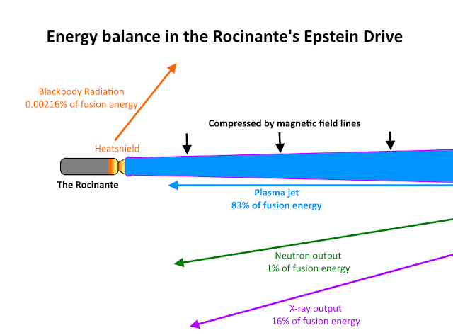 Putting these percentages so far together, 0.00216% of the fusion reaction energy ends up as heat in the heatshield.Using that percentage, it is now evident that we have a very large ‘multiplier’ to play with. For every watt that the heatshield can survive, 46,300 watts of fusion output can be produced.A heatshield absorbing 2.09 GW of heat means that its Epstein drive can have an output of 96.8 TW. About 2.2kg of fuel is consumed per second.83% of that fusion power is in the form of useful charged particles, and the magnetic field turns 75% of those into thrust. So, 41.5% of the fusion power becomes thrust power; which is 60.25 TW.The effective exhaust velocity of a Deuterium-Helium3 reaction can be as high as 8.9% of the speed of light. This assumes 100% burnup of the fusion fuel. Because we are using an excess of Helium-3, this might be reduced to 6.3% of the speed of light.With this exhaust velocity, we get a thrust of 6.37 MegaNewtons.An empty 250 ton Rocinante would accelerate at 2.6g with this thrust.We know it can accelerate harder than that but it cannot handle any more fusion power. So, it must increase its thrust by injecting water alongside fuel into its exhaust.There is a linear relationship between exhaust velocity and thrust at the same power level, but a square relationship between thrust and mass flow.Halving the exhaust velocity doubles the thrust but quadruples the mass flow rate. The Rocinante can have a ‘cruise’ mode where only fuel is consumed to maximize exhaust velocity, and a ‘boost’ mode where more and more water can be added to the exhaust to increase thrust.It is useful to know this, as we must now work out just how much fuel (Deuterium and Helium-3) and extra propellant (water) it needs1800km/s is done in the ‘boost’ mode, and then 2200km/s in the ‘cruise’ mode, for a total of 4000km/s. How much fuel and propellant does it need?As with any rocket equation calculation, we need to work backwards.Mass ratio = e^(DeltaV/Exhaust Velocity)An exhaust velocity of 6.3% of the speed of light and a deltaV requirement of 2200km/s means a mass ratio of 1.123.The 250 ton Rocinante needs to first be filled with 30.75 tons of fusion fuel. A 1:2 mix of Deuterium (205kg/m^3) and Helium-3 (59kg/m^3; it won't freeze) has an average density of 107.6kg/m^3, so this amount of fuel occupies 285m^3. It represents about 4.9% of the spaceship’s 12x12x40 m internal volume.
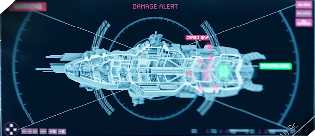 And now the ‘boost’ mode. 5g of acceleration while the spaceships gets lighter as propellant is being expended means that thrust decreases and exhaust velocity increases gradually over the course of the engine burn. The propellant load can to be solved iteratively... on a spreadsheet.Using 0.25 ton steps for water loaded onto the Rocinante, it can be worked out that an initial mass of 352 tons is required. This represents an additional 57 tons of water and 17.25 tons of fuel.The full load is therefore 57 tons of water in 57m^3, and 48 tons of fusion fuel in 446m^3. Together, they fill up 8.7% of the Rocinante’s internal volume.The thrust level during the acceleration to 1800km/s varies between 13.77MN and 17.27MN. It takes just over 10 hours to use up all the water.Boosting to 12g would require that this thrust be increased further, between 33.05MN and 41.44MN. However, it could only be sustained for 106 minutes, until 751km/s is reached.
In ‘cruise’ mode and with no water loaded, the Rocinante would have 3320km/s of deltaV and can cross the distance between Earth and Saturn in 10 to 12 days at any time of the year.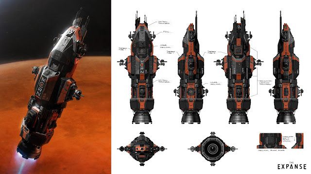
Official art by Ryan Dening. At 12g, it can sprint out to a distance of 21.2 thousand kilometres in about 10 minutes, and 0.76 million kilometres in an hour.
Scaling
This proposed design can be easily scaled to adjust for different figures for mass, acceleration and deltaV.
The variable will be the ignition point distance from the spaceship and therefore the magnetic field strength of the coils in the 'nozzle'. A stronger field allows for fusion products to be redirected from further away, so that an even smaller portion of the harmful energies are intercepted.
If we assumed a ten times greater density for the Rocinante, for example, we would have an empty mass of 2500 tons. To adjust for this while maintaining the same performance, we would simply state that the fusion reaction is ignited 10^0.5: 3.16 times further away, or 948m. The 'multiplier' mentioned earlier jumps from 46,300 to 461,300, just over 10 times better than before. In other words, the fusion output can be increased 10 times and all the performance falls back in line with what was calculated so far.ConsequencesBeyond what we’ve seen on the show or read from the books, there could be some interesting consequences to having this sort of design.Visually, for example, the rear end of spaceships would glow white hot. They cannot come close to each other while under full power, as then they’d expose each other’s flanks to intense heat from the fusion reactions.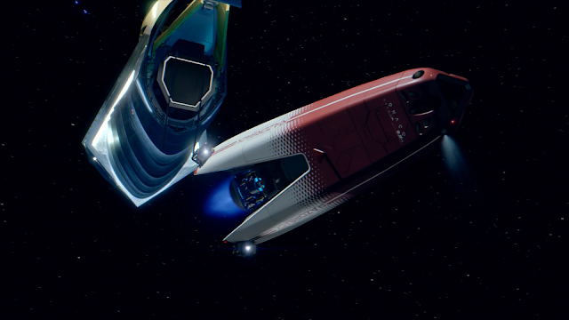 You might have noticed from a previous diagram that a portion of the fusion plasma travels all the way up the magnetic fields without being redirected. This could be the reason why we see 'gas' in the 'nozzle'; it is simply the leaking plasma hitting a physical structure and being compression heated up to visible temperatures.
 A failure of the magnetic fields would immediately subject the heatshield to 5x its expected heat intensity. This would quickly raise the temperature by a factor 2.23, so it would turn from solid to explosively expanding gas. Not exactly a ‘failure of the magnetic bottle’, but a similarly devastating result.On the other hand, the magnetic field passively provides shielding against most of the radiation that can affect space travellers. If it is strong enough to repel fusion protons, then it could easily deal with solar wind protons and other charged particles, as found in the radiation belts around Earth or Jupiter. This could be a reason why we don’t see thick blankets of radiation shielding all around the hull.Our proposed engine design is pulsed in nature. We want smooth acceleration, so we want as many small pulses in such quick succession that the spaceship feels a near-continuous push. This can be achieved with as few as 10 pulses per second, or hundreds if possible.However, even at 10 pulses per second, you need to shoot your fusion fuel from the fuel stores to the ignition point 300 meters away at a velocity of 3km/s. This is can be accomplished by a railgun, and it is incidentally a good fraction of the projectile velocities used in combat.
 Could the Belters in the Expanse simple have pointed their fuel injection railguns in the opposite direction to equip themselves with their first weapons?Similarly, an intense laser is needed to ignite the fuel quickly enough to achieve an extreme fusion gain. Doing so from 300m away requires a short wavelength and a focusing mirror… which are also the components needed to weaponize a laser. If a laser can blast a fuel hard enough to cause it to ignite, then it could do the same to pieces of enemy spaceships, and all that is needed to extend the range is a bigger mirror.There is also a claim made where the Rocinante’s fuel reserves are ‘enough for 30 years’. This cannot mean propulsion. Even at a paltry 0.1g of acceleration in ‘cruise’ mode, the Rocinante can consume all of its fuel in just 40 days. Add in a lot of drifting through space without acceleration, and we’re still looking at perhaps a year of propulsion. It is much more likely that this claim refers to running the spaceship; keeping the lights on, the life support running and the computers working. That sort of electrical demand is easily met by the energy content of fusion fuels.Finally, keep in mind that the propulsion technology described here is not specific to the setting of the Expanse. It respects physics and you can introduce it to any setting where real physics apply. In other words, it is a ready-made and scalable solution for having rapid travel around the Solar System without much worry about propellant, radiators, radiation shielding and other such problems!
 -
Good progress. Wish I could 'Like'.
-
15 hours ago, Nothalogh said:
Not exactly what I was insinuating, I was more proposing the use of the syngas byproduct as propellant
OK, that works.
The question becomes how you have enough raw material to make a noticeable impact on the spaceship's mass ratio to consider this an option.
-
4 hours ago, farmerben said:
I've remarked before, all the images of the arcjet seem to have made a basic sign error. We want the positive electrode at the front of the engine and the negative behind.
If we don't need electrodes to create the ionization state, then they don't have to be in the combustion chamber. They could be around the outside of the thermal engine.
The basic idea is to increase the kinetic energy of positive ions, at the cost of pulling electrons back toward the ship. In order to balance that we need electron guns parallel to the exhaust stream. I'm not sure if we need electrodes at all. The entire spacecraft can act as the positive electrode, and a virtual negative electrode is created behind the spacecraft.
We can do this now. Just attach electron guns parallel to any engine, and get a small boost. I'm not sure if we can run a huge amount of continuous power at present technology levels, but there seems to be room to improve electron guns.
The arcjet is not an electrostatic engine, nor does it eject electrons. The exhaust is neutral.
An arcjet works by creating an electrical arc between the cathode and anode. The electrons bump into exhaust gas particles and cause them to heat up, which is it is an electrothermal propulsion system.
-
I have several ideas on how to expand on the NTER concept, specifically to make it work with very high temperature variants of nuclear thermal rockets (like gas cores) or in an atmosphere (using the electricity to drive a fan, for example).
An NTER-like power station where electrical power is used to boost plasma temperatures to 5000K+ would help perform plasma gasification very efficiently, but having to run the raw materials through your nuclear reactor in the first place is going to be quite difficult. Water, for example, is horrendously corrosive and would destroy most reactors well before it decomposes.
-
I'll do a bit of maths.
The main job of the active cooling is to absorb heat reaching the reactor chamber walls. The propellant flow does a good job of protecting it from thermal radiation, but X-rays and neutrons punch through. From gas-core NTR documents I've read, about 7% of the reactor power ends up in the walls.
Your hydrogen-propellant engine in high Isp mode has an engine power of 3568 * 9.81 * 3500 * 1000 /2 = 61.25GW. If this is 93% of the output, then the heat reaching the reaction chamber walls is about 4.6GW.
You mass flow is 3500 * 1000 / (3568*9.81) = 100kg/s.A beryllium oxide moderated gas core reactor can only handle a wall temperature of 1400K. Heating hydrogen from liquid to 1400K absorbs 20.3MJ/kg. Therefore, your hydrogen mass flow can only support 2GW of heating, which is an engine power of 26.9GW. I suggest you cut your thrust to 43.9% of its current value, or 1539kN.
-
57 minutes ago, jinnantonix said:
Nuclear engines (NTERs) provide an excellent solution for powering a re-usable tug for moving payloads from LEO and lunar surface to lunar orbit, asteroid research and even Mars. They can use hydrogen or methane propellant for initial burn from Earth (utilising the Oberth effect), and potentially use ammonia as it requires smaller, lighter tanks, and remains stable and easy to store without cryogenics for long term flights. Using nuclear power means the craft can visit deep space or in the shadows of planets and moons since not reliant on solar power. A nuclear tug without the need for angling solar panels can more easily spin to create artificial gravity. If NASA is successful in establishing mining on on the moon, nuclear electric power generation will be required to power the mining, milling and enrichment process, and nuclear tugs offer a good solution for launching the fuel to lunar orbit and beyond.
You make a good point. An NTER can choose to switch propellants during its trip!
-
@TiktaalikDreamingReally great work, especially with the radiation modeling.
From the Isp figures on the hydrogen propellant version, I work out that the temperatures here are about 30,000K.
Hydrocarbon fuels are certain to completely decompose at that temperature. Kerosene, when split into carbon and hydrogen, becomes a plasma with an average molar mass of about 4.66g/mol. This means that your exhaust velocity would drop by a factor 4.66^0.5 = 2.16In other words, you can actually push your liquid fuel version to an Isp of 1652s!
-
Hi! This is from the latest ToughSF blogpost here: http://toughsf.blogspot.com/2019/09/nter-nuclear-thermal-electric-rocket.html
NTER: Nuclear Thermal-Electric Rocket
There is a type of nuclear propulsion that can have most of the acceleration of a nuclear thermal rocket but also the high Isp of an electric thruster. Let’s have a look at nuclear ‘thermal-electric’ engines and their advantages.The title image is from 'dV: Rings of Saturn', here.Limits of Nuclear Thermal RocketsNuclear thermal rockets (NTR) work by heating up a propellant. Heat flows from the nuclear fuel to the propellant, raising its temperature. The higher the temperature, the faster the propellant expands in a nozzle, allowing for higher exhaust velocities.
 It is evident that higher temperatures allow for higher exhaust velocities. Nuclear rocket designs have always tried to push the temperatures up to the limit that their materials can handle.From Project Rover, we have 2750K as the maximum temperature that was sustained. This is not enough to break up the hydrogen propellant into individual H ions, so the exhaust velocity they could have achieved in vacuum is 8.86km/s or an Isp of 904s.
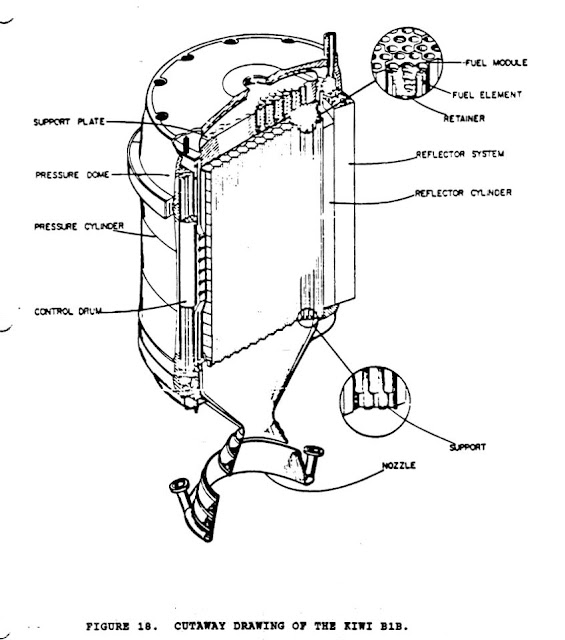 Project Timberwind went further with carbide fuel particles that could handle 3100K, and the Russian nuclear space program ramped up the temperatures to 3500K.
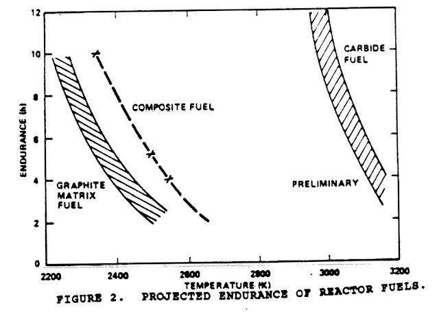 By operating at these higher temperatures, they gain a major step up in exhaust velocity by causing the hydrogen propellant to thermally decompose. The result is an exhaust with half the molar mass.
 At 3500K, an exhaust velocity of 12km/s is possible, which is an Isp of 1233s.This of course is an excellent level of performance. An exhaust velocity four times greater than that of chemical rockets but with propulsion systems with a similar power density means that spacecraft can perform missions with four times the deltaV requirements.For example, a hydrogen-propelled nuclear thermal spaceship with the same overall mass as a chemical-fuel spaceship could go to the Moon and back four times or reach Mars twice as fast.But what if we wanted to go even further?This is where the limits of nuclear thermal rockets impose themselves.At temperatures over 3200K, you must accept that the nuclear fuel will get eaten away by hot hydrogen because the protective materials used to shield the uranium fuel, such as Zirconium or Niobium ceramics, fail.At 4000K, the use of carbon materials is unsustainable as carbon readily vaporizes even without being attacked by superheated propellant. Perhaps temperatures as high as 4500K are possible with the most heat-resistant material we’ve discovered yet; Tantalum Hafnium Carbide.But, even at 4500K, the exhaust velocity achievable is 13.7km/s, only 14% better than with the conventional materials.A known solution to this to accept that the reactor will melt, or even operate in a gaseous state. This is the idea behind liquid core or gaseous core rockets.A liquid or vapor core nuclear rocket can produce core temperatures as high as 6000K.
 A gas core rocket can produce even higher temperatures.
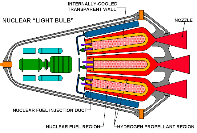 These are promising solutions, but we will not be focusing on them in this post. They have problems of their own, such as spewing out radioactive fuel along with the propellant, and have not yet been demonstrated to work.Instead, let’s look at the real world alternative.The Nuclear Electric AlternativeIf the temperatures required to achieve higher exhaust velocities are too great to handle, then it is smart to side-step the challenge and use another form of propulsion.
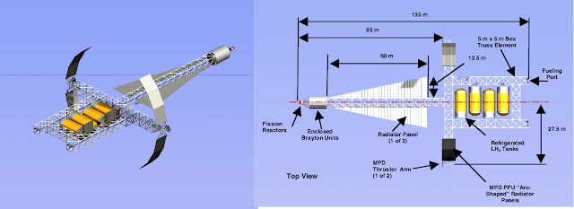 Electric propulsion does not heat up the propellant but accelerates it in other ways. Exhaust velocities of 60km/s are being produced by space probes right now, and 210km/s has been demonstrated.Nuclear reactors are the preferred method for providing a reliable source of power in space that does not depend on distance from the Sun or finite stores of chemical fuels. A few dozen kilograms of uranium can release megawatts for years.This power can be converted into electricity by moving heat from a high temperature (reactor) to a low temperature (radiator) and forcing the temperature gradient to do work with something like a turbine.The efficiency of the process depends on how work is extracted. A thermoelectric device might have an efficiency of 10%, a turbine 40% and a magnetohydrodynamic generator 60%. These efficiencies are lower than those on the ground because we have to reduce the temperature gradient and maintain the cold end (the radiators) at a relatively high temperature so that the cooling surfaces required stay manageable.
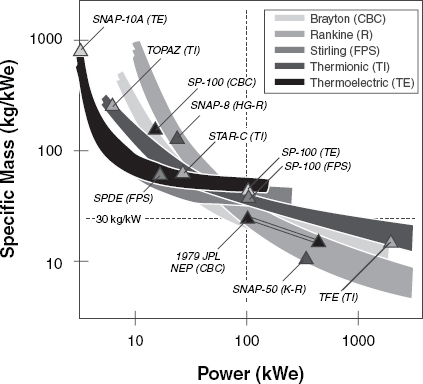 Radiating away the heat from a 100 Megawatt heat source at 400 Kelvin would need the spaceship to extend radiator surfaces totalling 69,000m^2. Even lightweight carbon fins would impose a mass of 345 tons, and this is without the pumps and piping required to move the heat around. Increasing the radiator temperature to 800 Kelvin might halve the generator’s output but it would reduce the radiator mass down to 43 tons. When dealing with spacecraft that are very sensitive to mass increases (as each kg gained requires exponentially more kg of propellant to be added), this is a worthwhile tradeoff.The electricity generated is then used to power an electric propulsion system.‘Ion’ or ‘plasma’ engines are of this sort. They feature very high exhaust velocity but very low power density. While a nuclear thermal rocket enjoys 100kW to 1MW per kg, an electric engine would struggle to produce more than 2kW per kg. Most modern examples achieve less than 1 kW per kg.
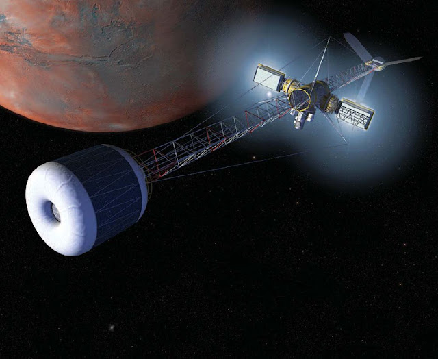 The low power density of the electric propulsion system, the mass of the radiators and mass of equipment like turbines all add up to create a nuclear-electric rocket (NER) where each kW of power is paid for by several kilograms of mass.This, coupled with the higher exhaust velocities cutting thrust (exhaust velocity and thrust have an inverse relationship), means spacecraft that necessarily accelerate very slowly. Uncrewed cargo craft won’t mind the wait. Human transports and crewed ships would prefer to use much more propellant to speed up their interplanetary trips.
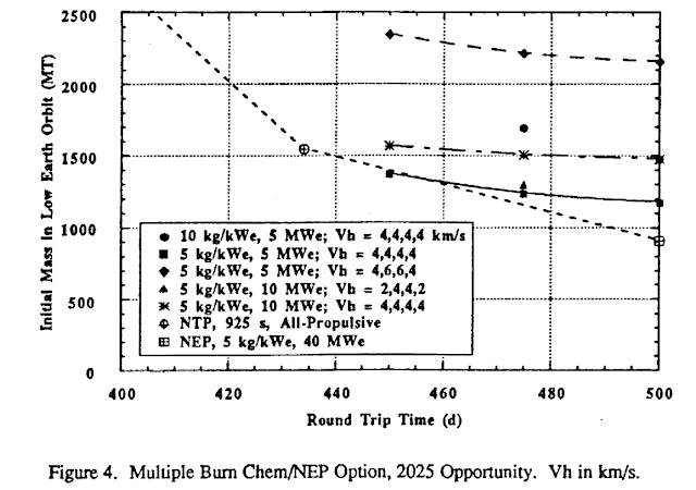 The poor Bimodal rocketThere have been attempts at trying to gain the benefits of both nuclear thermal and nuclear electric propulsion.
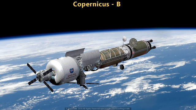 A previously proposed solution is the bimodal rocket (BNTR). In one mode, it is a thermal rocket. In another mode, it is a reactor the provides heat to a generator that powers an electric propulsion system.
The advantage is that it can perform a high-powered burn out of inner orbits and deep gravity wells, like our Low Earth Orbit, maximizing Oberth gains. It then slowly increases its velocity with a high Isp electric engine to shorten its interplanetary trip.The problem with this approach is that switching between the two modes of propulsion requires that equipment for both types be present at all times. This means that you need the nozzle of a nuclear thermal rocket as well as the radiators for an electrical generating system. The equipment for the mode not in use becomes dead weight.Furthermore, nuclear cores cannot be made hot and powerful for the thermal mode as well as stable and endurant for the electric mode. The 3000K+ temperatures and high pressures that made a good nuclear thermal mode clash with the need to reduce temperatures and protect the nuclear fuel so that it can provide heat for days to months on end. All designs end up compromising on performance.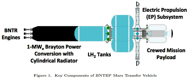 The result is sub-optimal performance in either mode. A lower temperature thermal mode with diminished Isp and thrust, and a reduced efficiency electric mode with diminished power output.The true hybrid
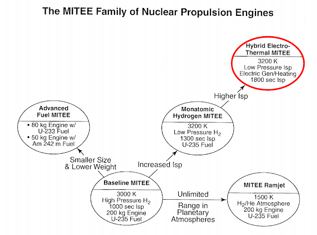 The nuclear thermal-electric rocket (NTER) design is meant to combine the two different types of propulsion into a true hybrid that does not waste the fact that cryogenic propellants are wasting their cooling capacity (as Alan Bond put it) in NTRs and NERs.There are many variants possible, but we will explain the design using one of the most promising of them: the intercooled Brayton-cycle nuclear thermal-electric rocket with magnetohydrodynamic booster. It will be using liquid hydrogen as propellant.
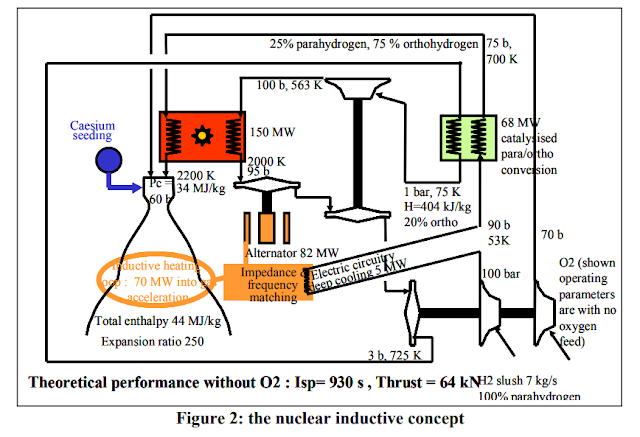 Let’s follow the journey of the liquid hydrogen from the propellant tanks, through the nuclear electro-thermal rocket and out of the nozzle. The pressure, temperature and other numbers being mentioned are only indicative of what would be expected from this design.
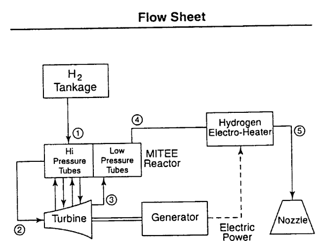 The short version is that the hydrogen makes two passes through the reactor core. Once at high pressure, another time at low pressure. Many megajoules of energy are extracted from each kilogram of hydrogen that makes these loops. The energy is converted into electricity, which is used to further accelerate the thermal exhaust going down the nozzle using an electric booster.1-Cooling
 The hydrogen starts out as a cryogenic fluid. A small impeller or autogenous pressurization of the propellant tanks pushes it out at a low pressure.
The fluid passes through a heat exchanger. It absorbs heat from one of the steps below and becomes a cool gas (perhaps 150 Kelvin) with low pressure (1 bar).About 2.2 MJ of heat is absorbed for every 1 kg of hydrogen that passes through.2 – CompressionThe cool hydrogen gas can now pass through a two-staged compressor.The first stage multiplies the pressure 50-fold. It releases the hydrogen at a pressure of 50 bar. Compression heating raises the gas’s temperature to 468K. We use temperature changes to track how much energy is consumed or released, as pressure differences are recovered in later steps. The first stage of the compressor requires 4.54 MJ of energy per kg of hydrogen.The warm hydrogen passes through an intercooler. This is where the heat absorbing ability of cryogenic hydrogen is exploited. Liquid hydrogen from the propellant tanks is used to bring the 50 bar hydrogen’s temperature down to 313K.The second stage compressor multiplies the pressure 3 times. It produces warm hydrogen gas at 150 bars and a temperature of 430K. It would require 1.68MJ/kg of hydrogen.The total energy consumed by the compressor stages is 6.22MJ/kg.3 – High pressure heatingThe warm hydrogen enters the high pressure section of the reactor core. By passing over the fuel elements, it absorbs energy and reaches a temperature very close to that of the uranium fuel itself. In this example, it will be 2500K.4 – ExpansionThe hot hydrogen enters a turbine. It expands, decreasing in pressure and temperature. The turbine blades are propelled by the hydrogen’s expansion to extract 29.18MJ/kg. The blades will need to be hollow so that they can be actively cooled in order to survive the initial 2500K temperatures.Hydrogen exits the turbine at a temperature of 698K and a pressure of 1 bar.5 – GeneratorThe turbine and compressors are connected by a single shaft. That shaft can be connected to an electric generator. Energy consumed by the compressors and extracted at the turbine allows for a net gain. In this example, it is 22.96MJ/kg.6 – Low pressure heatingThe turbine’s exhaust now passes through the low pressure segment of the reactor. It is heated again to 2500K and Cesium is added. The Cesium would represent a tiny portion of the hydrogen flow (0.1% or less by mass) but greatly increase its electrical conductivity.7 – Nozzle with boosterThe nozzle is ringed with electromagnets. They act upon the conducting exhaust gases like an electric plasma rocket to further accelerate the exhaust. Electricity comes from the turbine-driven generator.Without any electric boost and a large vacuum-optimized nozzle, the rocket’s exhaust velocity would be 8.45km/s, which is an Isp of 862s. However, adding the 22.96MJ/kg gained from the generator allows for an exhaust velocity of 10.8km/s, or an Isp of 1104s!Naturally, this is an ideal scenario where everything is 100% efficient. It would more realistic to add perhaps just 17MJ/kg to the hydrogen, increasing the Isp to ‘only’ 1046s.This is still a very significant improvement. We are obtaining greatly improved Isp from a solid nuclear core, without the increase in temperatures that would otherwise be needed from a purely thermal rocket. On the contrary, the 2500K temperature allows for greatly improved core endurance and reduces thermal stresses on all components involved.Only one mention of this type of propulsion exists outside of a handful of scientific papers: the game “dV: Rings of Saturn”. It features plenty of hard SF technologies, including an example of this type of propulsion system. The engine is called the “Rosatom-Antonov K-37: Turbine Nuclear Thermal Rocket with Lorentz-effect accelerator” which uses the steps described above to achieve an exhaust velocity of 15km/s, impossible for a solid-core nuclear rocket otherwise.Here you can watch an excellent start-up sequence made for that engine.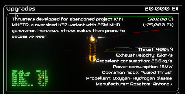
Nuclear Thermal-Electric Variants and PerformanceWe will now go through a list of potential variants, each with their own advantages and disadvantages, and work out a likely performance level. As the technology progresses or assumptions change, the performance that is calculated will also change. We will use a ‘near future’ set of performance assumptions and then extrapolate to a ‘further future’ where materials have improved and technology has progressed somewhat.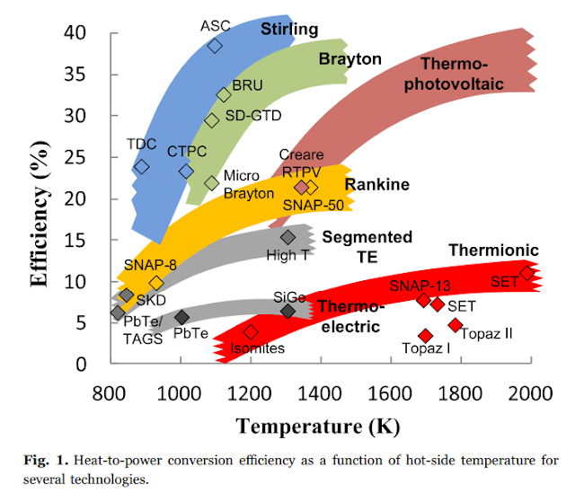 Simple ThermalIt is important to establish a reference point to see what the relative advantage the NETR has over the NTR.
 A large-scale engine that can be built from proven designs would achieve a power density of 1 MW/kg and operate at 2800K using current technology. This gives it an Isp of 912s (8.9km/s) using liquid hydrogen and 635s (6.2km/s) with liquid methane.A more advanced version would operate at a higher temperature and use stronger, lighter materials. 3200K core temperature allows for a liquid hydrogen Isp of 1214s (11.9km/s) and a liquid methane Isp of 679s (6.6km/s).Note that at this point, increasing the temperature up to the absolute limits of currently understood materials technology (<4200K) would only increase Isp by 15% over the advanced design, but the use of dense refractory ceramics would cut into the power density.ThermoelectricIn this variant, the Seebeck effect is used to generate electricity. A thermoelectric couple stands between a heat source and a cold sink so that the temperature gradient drives electrons to produce a current.
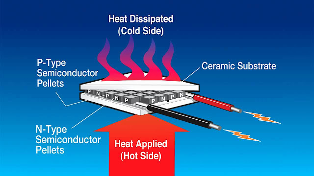 We have a >2800K heat source available and cryogenic propellants as the cold sink. No single thermoelectric generator can handle such a huge temperature gradient in one step. It is more likely that multiple generators are stacked on top of each other, each only handling a smaller temperature gradient. The maximum temperature that can be handled today by thermoelectric materials is about 1300K.Propellant would first need to be pumped to the stack of thermoelectric generators (TEGs) to keep the cold end at a low temperature. If it is 500K, then 7MJ/kg of cooling can be obtained from liquid hydrogen, and 1.43MJ/kg from liquid methane.Heat can be delivered to the top stack of thermoelectric generators by a heat pipe directly connected to the nuclear reactor’s core. It extracts electricity from the temperature difference between the hot end and the cold end. The ideal Carnot efficiency across 500 to 1300K is 61.5%.The efficiency of a thermoelectric device is given by:Efficiency = (1-Tc/Th) * ((1+ZT)^0.5 -1) / ((1+ZT)^0.5 + Tc/Th)Tc is the cold end temperature in Kelvin.Th is the hot end temperature in Kelvin.ZT is a characteristic value depending on the thermoelectric materials.Using modern thermoelectric materials with a ZT of 1.2 across to 500K to 1300K temperature range, an efficiency of 16% is to be expected.A negligible amount of inefficiency comes from having to pump the propellant through the piping from the propellant tanks, through the heat exchangers and into the reactor core.This means that the 7MJ cooling capacity of liquid hydrogen is spent handling the (1-0.16): 84% of reactor heat that is wasted. 1.33MJ becomes electrical energy. Liquid methane’s 1.43MJ/kg cooling capacity becomes 0.27MJ of electricity.An advanced thermoelectric generator that could handle 2000K temperatures and have a ZT=2 could raise its efficiency to 27%. It would extract 2.59MJ of electricity from the cooling capacity of hydrogen, and 0.53MJ from methane.
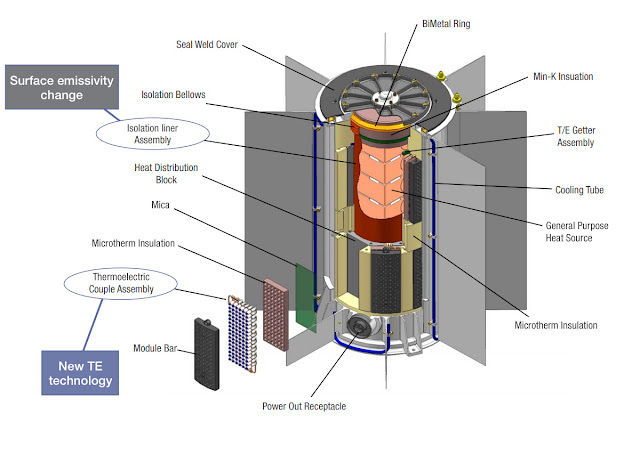 Advantages of this design include having nearly no moving parts and only a single passage of the propellant through the reactor. It would be tough and reliable. Tens of thousands of hours of operation are expected.Disadvantages are the low efficiency and great weight of the thermoelectric generators.ThermionicThe high temperatures available from the reactor core can cause metals to directly emit electrons. This is the thermionic effect that can be used to produce electricity.
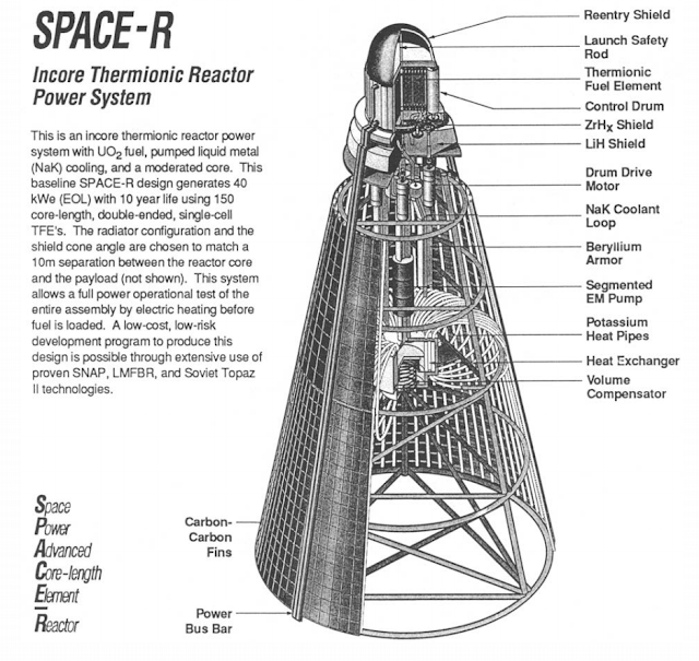 Two plates, an emitter and a receiver, are held close to each other. The emitter is heated to a high temperature, causing it to release electrons. Electrons jumping the gap between the two plates and are collected as an electrical current. However, the receiver absorbs all of the thermal radiation from the receiver, which is the main source of inefficiency. We want the temperature gap to be as high as possible, so a receiver with a low emittance and low temperature is ideal. The emitter can be made of materials like molybdenum or tungsten; in fact, it is even more temperature resistant than the nuclear core and can therefore be as hot as we want. The cold end is a problem though.
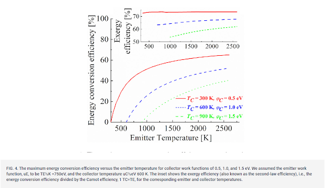 In previous examples of nuclear thermionic power, having a low temperature receiver conflicted with the need to have a high radiator temperature to get rid of the waste heat into vacuum. We have access to cryogenic propellant which can absorb heat even at very low temperatures, so this is not as much of a problem.We know that high efficiencies are already possible. A Japanese solar propulsion research effort produced a thermionic converter (TIC) that held an emitter at 1850K and cooled the collector to 1100K. They managed 57% of the maximal Carnot efficiency, resulting in 23.2% actual efficiency.A modern nuclear thermo-electric rocket using a thermionic converter could raise an emitter’s temperature to 2700K, only slightly less than the core temperature by using heat pipes, which do not require any electricity to move heat (only a temperature difference).An electric pump or exhaust bypass drives a low pressure pump to push propellant through a heat exchanger that cools the thermionic collector. It could hold it at 1000K.The maximum Carnot efficiency across this temperature gradient is 64.3%. Near term performance might be 30% of this maximum, achieving 19.3%.Hydrogen can absorb 14.2MJ/kg when heated from liquid to 1000K. With the thermionic converter’s efficiency, we can produce 3.4MJ of electricity from each kilogram of hydrogen.Methane absorbs 3.4MJ/kg in the same situation, which allows 0.81MJ of electricity to be produced.The hot gases from the collector are then sent into the reactor to be heated themselves up to the 2800K core temperature, and then pushed through a nozzle.The electricity produced by the thermionic is then used to accelerate the exhaust from the nozzle.An advanced version of this is might manage to achieve 60% of the ideal Carnot efficiency between 3200K and 1000K, for an actual efficiency will of 41.2%.Hydrogen now allows 9.9MJ of electricity to produced and methane allows for 2.4MJ.The advantages of this design are that it can handle very high temperatures and extract more power using the cryogenic propellants. It is just as resistant to damage as the thermoelectric option.Disadvantages are low power density, although much better than a thermoelectric converter.One thermionic variant attempts to use three thermionic steps, all with the same emitter temperature but at higher and higher collector temperatures. Propellant gas moves from step to step, making the most of its cooling capacity in a sort of cascade.For example, the first step could have the emitter at 2800K and the receiver at 500K. The second has the receiver at 1000K and the final step has the receiver at 1500K.
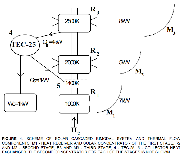 Continuing with the assumptions of the previous variant, thermionic efficiency between 2800K and 500K can be as high as 24.6%. Heating hydrogen from liquid to 500K absorbs 7MJ/kg, so 2.3MJ of electricity can be produced at this step.The second step recycles the warm gases released from the first step and further heats them to 1000K. Another 7.35MJ/kg of cooling capacity is available, of which 1.76MJ can be extracted as electricity if we expect a thermionic efficiency of 19.3%.In a third step, we further heat the hydrogen to 1500K. Thermionic efficiency falls to 13.9%, which is still enough to gain another 1.25MJ from the hydrogen.A total of 5.3MJ of electricity of produced.Re-doing the numbers for methane, we generate 0.47+0.45+0.41: 1.33MJ.An advanced version might achieve 60% of the Carnot ideal, operate at a higher 3200K emitter temperature and add a 4th stage that raises the collector temperature to 2000K.The efficiencies of the stages are 50.6%, 41.2%, 31.8% and 22.5% with collector temperatures at 500, 1000, 1500 and 2000K.The electrical power generated at each stage using 1kg of hydrogen would be 7.2MJ, 5.2MJ, 3.6MJ and 2.4MJ for a total of 18.4MJ.The same figures for methane would be 2.5MJ, 1.3MJ, 1.2MJ and 0.87MJ, totalling 5.87MJ.
Clearly the advantage here is that the cooling capacity of the propellant is used much more efficiently. However, multiple thermionic converters would mean a reduction in overall power density.Thermoelectric generators are limited in the maximum temperature they can handle. This limit can be broken by another variant, a hybrid having the collector of a thermionic converter act as the hot end of a thermoelectric generator. Cryogenic propellant can first cool the cold end of a thermoelectric generator to 500K. The resulting warm gas is then used to cool the collector of a thermionic receiver to 1300K. This hotter gas passes over the hot end of the thermoelectric generator before entering the reactor core. The thermionic emitter meanwhile is directly heated by the nuclear reactor to 2800K.
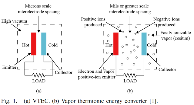 Thermionic efficiency can be as high as 16% between 1300K and 2800K. Thermoelectric efficiency would also be 16% between 500K and 1300K.
Starting with hydrogen, we work out that the thermoelectric generator produces 1.33MJ of electricity, and the thermionic converter produces another 2.29MJ for a total of 3.6MJ.Methane following the same path allows for the production of 0.27MJ and 0.63MJ, totalling 0.9MJ of electricity.An advanced version of this with an improved thermoelectric generator of ZT=2 operating between 500K and 2000K, and a higher temperature thermionic converter working between 2000K and 3200K, would have efficiencies of 27% and 17% respectively.It would extract 2.59MJ and 4.83MJ of electricity from each stage for each kg of hydrogen, a total of 7.4MJ. Each kg of methane yields 1.95MJ of electricity.Also, thermionics can work with other power conversion systems to achieve a very high overall efficiency.
Thermionic efficiency can be as high as 16% between 1300K and 2800K. Thermoelectric efficiency would also be 16% between 500K and 1300K.
Starting with hydrogen, we work out that the thermoelectric generator produces 1.33MJ of electricity, and the thermionic converter produces another 2.29MJ for a total of 3.6MJ.Methane following the same path allows for the production of 0.27MJ and 0.63MJ, totalling 0.9MJ of electricity.An advanced version of this with an improved thermoelectric generator of ZT=2 operating between 500K and 2000K, and a higher temperature thermionic converter working between 2000K and 3200K, would have efficiencies of 27% and 17% respectively.It would extract 2.59MJ and 4.83MJ of electricity from each stage for each kg of hydrogen, a total of 7.4MJ. Each kg of methane yields 1.95MJ of electricity.Also, thermionics can work with other power conversion systems to achieve a very high overall efficiency.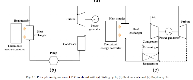 ThermophotovoltaicWhereas the blackbody radiation from a high temperature thermionic emitter is a source of inefficiency, it can be used to produce electricity using thermophotovoltaic panels (TPV). A thermophotovoltaic cell works like a photovoltaic cells, found in solar panels, except that it can convert the wavelengths released by surface less bright than the Sun into electricity.
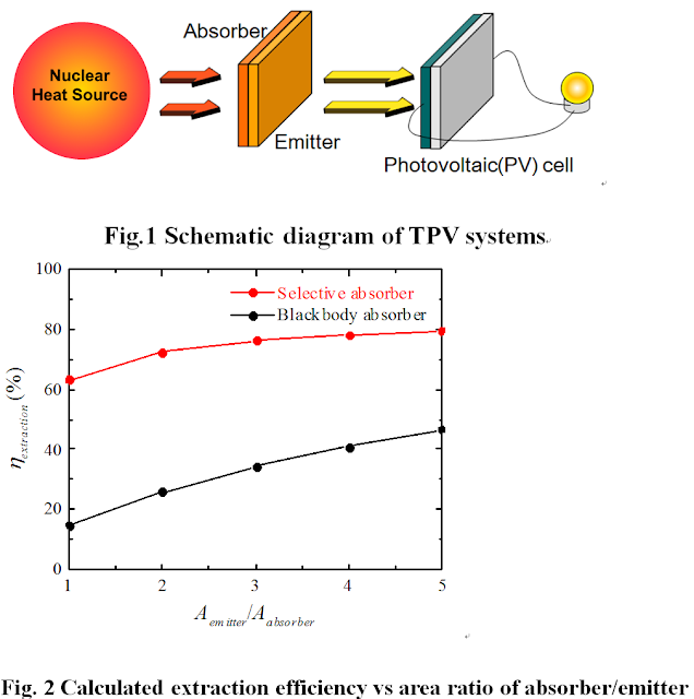 Current work focuses on increasing the efficiency of thermophotovoltaic systems using emitters at lower temperatures (1000 to 2000K), with efficiencies of 25 to 38% predicted. However, we can have a 2800K emitter directly heated by a nuclear reactor, emitting wavelengths with a peak at 1000 nanometers. The conversion efficiency can be as high as 56% using multi-junction Gallium-Indium-Arsenic-Phosphorus photovoltaic cells. As has been mentioned in a previous ToughSF post, efficiencies as high as 61% have been demonstrated.The thermal radiation reaching these photovoltaic cells heats them up. Hot photovoltaics quickly lose efficiency. It is therefore important to maintain a temperature of about 300K, which we will accomplish using cryogenic propellant as a heatsink.Using an efficiency of 50%, we find that a very high temperature thermophotovoltaic system can produce 4.2MJ of electricity when using liquid hydrogen as the heatsink.
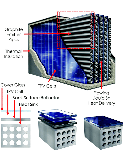 An advanced version of this set-up is very unlikely to increase the efficiencies or temperatures much further. Power density could become better though.
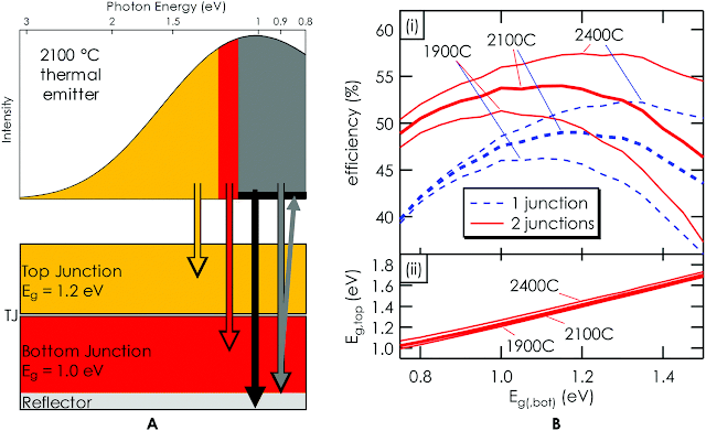 The advantage of thermophotovoltaics is their good power density relative to thermoelectric or thermionic devices and an excellent overall efficiency.However, having to operate at low temperatures means that only a portion of the cryogenic propellant’s cooling capacity is utilized.StirlingWe now move to a very different method of generating electricity. It works using two pistons that exchange gases as one heats up and the other cools down. The motion of the pistons drive a generator.The Stirling cycle is currently the largest working type of nuclear power generation for space, with NASA’s ‘Kilopower’. We can cite from a test report on the design: “The engine thermal efficiency ranged from 30-34% at approximately 50% of Carnot”.
 This is an interesting piece of information. It tells us that if have Stirling generator (STG) with the appropriate materials (perhaps tungsten carbide with an inert helium gas as the working fluid), we could have the hot end be directly heated by a nuclear core to 2800K, and the cold end by cooled by cryogenic propellant.
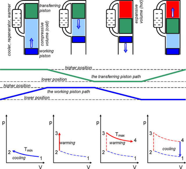 A 1000K cold end means that the Stirling generators works across a 2800K to 1000K temperature gradient, allowing for a maximum Carnot efficiency of 64%. If the generator manages half of this maximum efficiency, we get 32%.
The cooling capacity of liquid hydrogen heated up to 1000K is 14.2MJ/kg. 32% efficiency means that 6.7MJ of electricity can be produced for every kg of hydrogen used.
Using liquid methane allows for 1.6MJ of electricity to be produced.A more advanced Stirling design would use a free piston inside a linear generator to achieve 63% of the Carnot maximum. When paired with a 3200K hot end from a higher temperature nuclear core and the same 1000K cold end as previously, we can expect an overall efficiency of 43%.The electricity that can be generated when using hydrogen increases to 10.7MJ, and with methane to 2.6MJ. The main advantage of Stirling generators is that they can achieve a better percentage of the maximum Carnot efficiency and have generally better power densities than the alternatives. The gas in the cylinders can be different from the coolants used to increase or reduce their temperature, so they could theoretically handle very high temperatures without worry of chemical degradation.
The disadvantage though is that they work across a large temperature gradient, so they have to be made robust and therefore heavier, and they have several moving parts that reduce their operating lifetime. On spacecraft, they might need to include a vibration absorber.
Brayton IntercooledThis is the design we described earlier when explaining the nuclear thermal-electric concept. Propellant is used to drive a Brayton cycle. Energy is extracted from the temperature difference between the heat exchanger and the turbine exit and is used to drive a shaft which spins an electrical generator.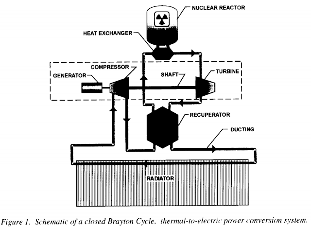 The process depends on a number of factors, such as the pressure ratio and the heat capacity of the gases involved. Therefore, it is not possible to use a simple percentage figure for the efficiency.
 Using the ‘modern’ nuclear core as out heat source, we would expect temperatures as high as 2800K to be used to maximize efficiency. However, turbine blades must bear the brunt of these temperatures. They have to spin at high speeds and maintain sufficient strength to not break off or slowly elongate. What’s worse is that with a turbine on a spaceship, it is not really possible to cool the turbine blades using cold air from the exterior or cold water from an endless reservoir. The result is hard limits on the temperatures that turbogenerators can work with.The highest a typical uncooled nickel-based turbine blade can handle is 1200K.
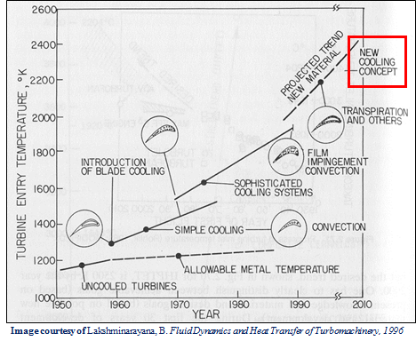 More recent alloys based on niobium have managed several hundreds of hours under 1700K conditions, but the best we have are silicon nitride or silicon carbide ceramics that have been tested for thousands of hours up to 2000K.
 Let’s run some numbers using hydrogen.We’ll start with two compressor stages, each increasing the gas pressure 10-fold. Temperature increases by a factor 1.95 after each stage. An intercooler between the stages absorbs some heat.If we set the entry temperature at 410K, the hydrogen will exit the first stage compressor at 800K. It enters the intercooler, where cold liquid hydrogen is used to absorb the heat added by the compression. The compressed gas is cooled down to 410K while the liquid hydrogen is heated into a 400K gas, ready to be sent into the compressor. 5.7MJ of heat energy is exchanged per kilogram. Going through the second stage compressor allows it to reach 100x the initial pressure and a temperature of 800K.We heat the hydrogen in the reactor core to 2000K.High pressure, high temperature hydrogen now enters the turbine stage to be expanded so that its energy can be extracted as mechanical work. Expanding across a 100-fold pressure difference lowers the temperature by a factor 3.8, so it exits at 526K.The compressors have consumed 11.4MJ to compress each kilogram of hydrogen. The turbine can extract 23.2MJ, so the net result is 11.8MJ for each kg of hydrogen. It is then converted into electricity by an alternator.If we apply real world efficiencies to these steps (95%, 90% and 95%), we are more likely to gain 8.4MJ instead. This is an overall efficiency of about 52%.The turbine exhaust goes through the reactor core again to be re-heated an exit through a nozzle, where the electrical energy gained is used to increase exhaust velocity.Methane in this same Brayton cycle consumes 1.1MJ/kg in the compressors, extracts 6.4MJ/kg in the turbine and gains a net of 5.3 MJ of electricity for each kilogram used. With a realistic overall efficiency of 56%, this is 4.4MJ.A more advanced turbine can use hollow turbine blades made of ceramic materials actively cooled by a liquid metal heat pipe. Hafnium carbide can form the outer layer while silicon carbide forms the core. This arrangement minimizes the use of the very dense hafnium-rhenium-tungsten alloy while exploiting the fact that the interior of the turbine blade can be kept at the <2000K temperatures where the lighter silicon carbide retains its strength.
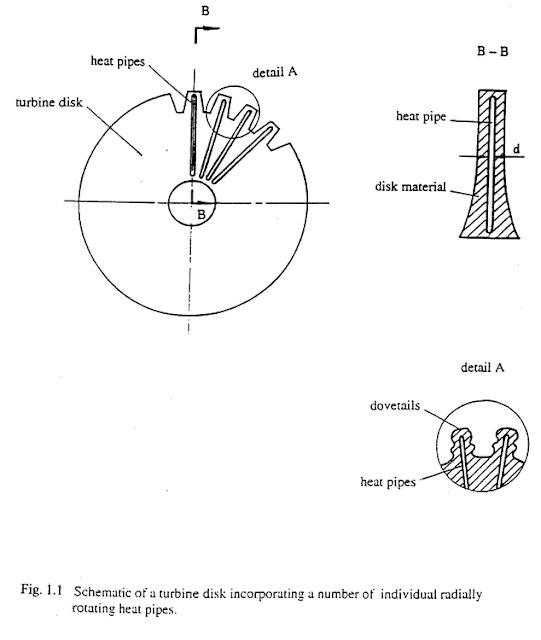 Active cooling is how we manage to increase turbine performance with existing materials, only that we are applying the concept here to much improved materials.Thanks to these improved materials, we can operate at 2800K.
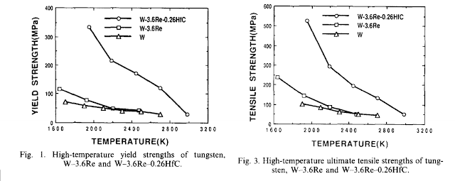 We will also use bigger compressors to reach even higher pressures, perhaps 500 times the initial pressure. This is similar to the performance of simple turbopumps on rocket engines today, like the Raptor, where pressure at the exit is 643 bar.To maximize the intercooling effect, we can separate the compression into three stages. In between each stage is an intercooler that makes use of the cryogenic propellant’s cooling capacity.Let’s run the numbers on a sample design.Three compressors aiming to multiply pressure 500-fold could be arranged to achieve 10x, 10x and 5x. This would increase the temperature of hydrogen gas 1.95x, 1.95x and 1.59x respectively.
 If hydrogen gas enters the turbine inlet at a temperature of 200K, it exits the first compressor stage at 390K. The compressor consumes 2.66MJ for every kilogram that passes through.The first intercooler reduces the hydrogen’s temperature back down to the compressor’s entry temperature. In a heat exchanger, hydrogen gas cools down from 390K down to 200K and cold propellant heats up from 22K to 166; this is an exchange of 2.66MJ of heat for every kilogram.The second compressor stage also consumes 2.66MJ/kg and releases 390K gas. It passes on the gases to a second intercooler that reduces their temperature to 358K. From the cold side of this intercooler’s heat exchanger, we get the gases at 200K that will go to feed the turbine inlet. From the hot side, we get the gases at 358K that will enter the final compression stage.In the third compressor, 3.1MJ are consumed and compression heating causes the hydrogen gas temperature to increase from 358K to 571K. The hot pressurized hydrogen is then fed into the nuclear reactor core.Hydrogen exiting the core sits at 2800K. A turbine expands it down a 500-fold pressure gradient. The expansion cools the hydrogen back down to 460K and 38.2MJ of energy can be extracted from each kg of hydrogen having passed through the turbine. It is converted into electricity by an alternator.The net energy produced as electricity in this design is 29.78MJ. With realistic efficiencies, this is 27.4MJ.We work out that the overall efficiency is 76%.Methane used in this design allows for a realistic energy gain of 8.4MJ/kg. Methane’s overall efficiency is 73%.A lot more energy is being extracted by these turbines for each kilogram of cryogenic propellant than with the previous generators. Turbines are also very lightweight for the power they handle, and they can be paired with electrical generators that are already achieving over 15kW/kg in power density. Superconducting versions of the latter could achieve 40kW/kg. Put together, we can see a power conversion system that exceeds the performance of previous examples ten-fold in terms of watts per kilogram of equipment mass.
 This advantageous level of performance is why turbomachinery is the preferred method of generating power on Earth and in space.One of the disadvantages of turbines using ceramic blades however is that they are brittle at lower temperatures and prone to cracking if heated up too quickly. They generally have a shorter lifetime than generators with few to no moving parts, shorter still if they start getting knocked around by impacts during combat or buffeting during re-entry.This makes turbomachinery relatively fragile.It is also possible to add a regenerator when the exhaust from the turbine is cooler than the gases going through compressors.For example, if the entry temperature to the compressor was 400K and the exit temperature was 781K, while the turbine exhaust temperature is 526K, like in the modern 2000K design above, then we use the turbine exhaust as the cold side of a heat exchanger and the compressor gas as the hot side.The regenerator allows these gases to reach an intermediate temperature. In this case, the average of 781K and 526K is 653K. The cooling effect on the compressor gas is therefore 128K. 1.8MJ of heat energy regenerated in this manner can reduce the need to use up the cryogenic propellant’s coolant capacity by the same amount. That cooling capacity can be better used elsewhere.In the advanced Brayton generator example described previously, two intercoolers are used between three compression stages. The first intercooler uses up most of the cryogenic propellant’s cooling capacity, so the second stage can only reduce the hydrogen gas’s temperature by 32K before it enters the third stage.Using a regenerator would have allowed a much more significant temperature reduction and a corresponding decrease in the compression consumption of the third compressor stage, as it would be working with cooler gases.This translates into significant portion of that saving ending up as more electricity at the end. The question however, is whether the increased weight from the regenerator allows for a gain in overall efficiency that does not significantly affect overall power density.The other variants possible using a Brayton cycle are a Double Loop design, where the exhaust of one turbine is fed into a second turbine, or a Closed Loop, where cryogenic hydrogen is only used to cool down turbine exhaust so that it can be recycled, much like a radiator would do.
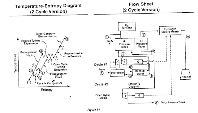 MagnetohydrodynamicThis is yet another completely different method of generating electricity. A magnetohydrodynamic generator (MHD) uses magnetic fields to slow down a conductor moving through it. The kinetic energy of the conductor is directly converted into electricity.
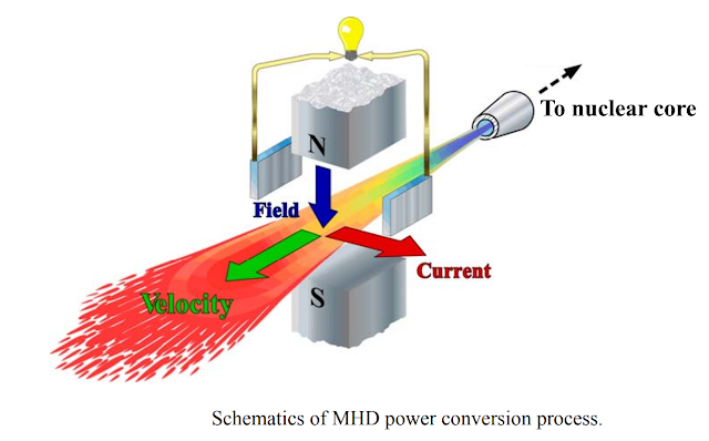 Hydrogen, methane or other good rocket propellants are not well suited for use directly in an MHD generator, as they need to be ionized to become good conductors (as plasmas), but this only occurs at very high temperatures. As they cool down while going through the MHD generator’s ducts, they become neutral gases again.
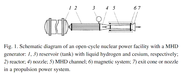 Several solutions have been proposed: seeding the propellant with elements that easily ionize at lower temperatures, ionizing the propellant with an electron beam or having a closed loop MHD generator where a separate fluid is kept.
 A closed loop is what we’ll focus on for now instead of the open cycle. It circulates an easily ionized element like cesium, potassium, rubidium or xenon between a heater, MHD duct, cooler and pump. The heater transfers thermal energy from the nuclear reactor core. Extreme temperatures are possible. The hot fluid travels down the MHD ducts, where some of its energy is extracted. In doing so, the fluid loses pressure and temperature. It then passes through a cooler, where we will bring in cryogenic propellant to act as a heatsink. The cooler fluid is then pumped back up to the design pressure to go through the loop again.
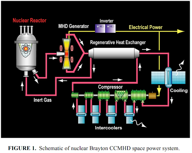 Technically, this is another Brayton cycle. Compared to a turbine, the MHD variant gains the ability to handle any temperature but loses the ability to extract most of the fluid’s energy. There are designs for MHD generators that work with 4000K temperatures and higher, something impossible to send through a turbine.Let’s consider a MHD generator realizable today.Helium is used, seeded with potassium. The hot end temperature is 2800K, like the reactor core providing the heat. The cold end temperature is limited by the point at which potassium stops being ionized and returns to being a neutral atom. This happens at about 1000K.
 This means that the maximum Carnot efficiency is 64%. Inefficiencies in the MHD generator and the pumping requirements means only about half of that is available, so overall efficiency is 32% with the help of intercoolers and regenerators.
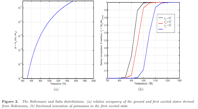 If we set the cooler temperature to 500K, then 7MJ/kg of cooling capacity can be obtained from liquid hydrogen, and 1.43MJ/kg from liquid methane.This translates into an electrical energy gain of 3.29MJ for each kilogram of liquid hydrogen consumed, or 0.67MJ for each kilogram of liquid methane.A lot more can be done with a more advanced MHD generator and a higher temperature nuclear reactor.For one, the helium/potassium mix can be heated to 3200K. This increases the maximum Carnot efficiency to 68.8%, assuming the same exit temperature of 1000K.We can also use superconducting magnets for the MHD generator and the electric motors turning the compressors. It might allow us to use an overall efficiency figure of 66%.
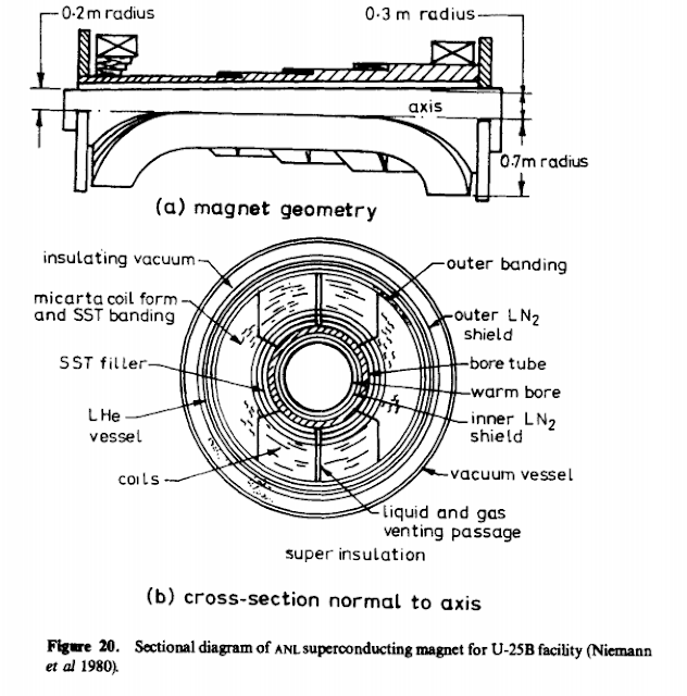 Putting all these advanced features together, and assuming a similar cooler temperature of 500K, we can manage to gain 13.5MJ from liquid hydrogen or 2.78MJ for liquid methane.Of course, the MHD generator cycle can be greatly improved. 1000K gases at the exit of the MHD duct are hot enough to drive another power generating cycle. It can be another Brayton cycle using a turbine, where we can extract another 40% of the remaining energy between 1000K and 500K, which would improve overall efficiency of the advanced MHD design to 79.6% (and the energy gain by a whopping factor of 1.66x, to 22.41MJ with liquid hydrogen and 4.6MJ with liquid methane). Or, a humble TEG device that can only obtain a few percent of the remaining energy but does not add any moving parts.There are several advantages to an MHD generator. It has a very high power density, no moving parts except for the pumps and the nuclear reactor would only need to have one single-pressure section that the propellant goes through once. It can easily be used as a topping cycle to power generating systems that cannot handle extreme temperatures but are able to use the MHD’s exhaust. In fact, it is best to have Magnetohydrodynamic, Brayton and Thermionic/Thermoelectric all working in series.Each cycle operates best at a certain temperature range. Magnetohydrodynamic generators thrive at extreme temperatures, turbines prefer lower temperatures that their turbine blades can handle, while thermoelectric generators can operate at low temperatures. Overall efficiencies using a 'combined' cycle approaches 80%. The highest power density combination is likely to be a turbo-MHD design.
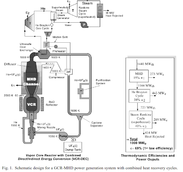 However, having a high temperature fluid mixed with reactive metals going round and round a loop will lead to corrosion issues that reduce the lifetime of the generator. The magnets, which need to stay cold to maximize efficiency, have to be placed right next to superheated gases. Superconducting magnets have even bigger issues with thermal management.
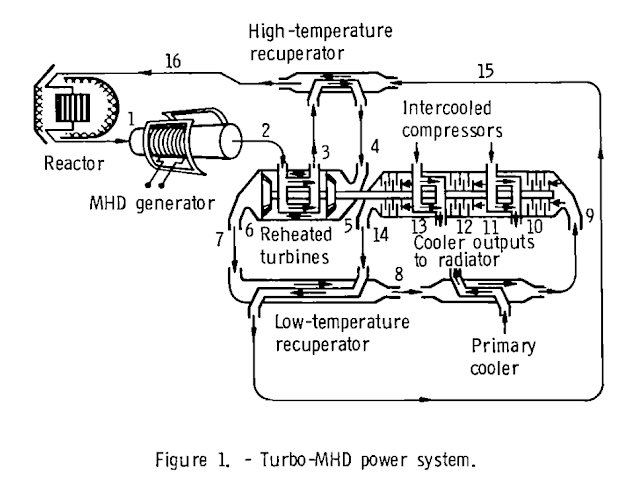 Electric boostersIn this section, we’ll have a look at how the electrical energy produced by the generators in the previous section can be employed to increase exhaust velocity.ResistoJetA resistojet is a simple heating device that has propellant run over tungsten or other refractory material so that temperature is increased through conduction.
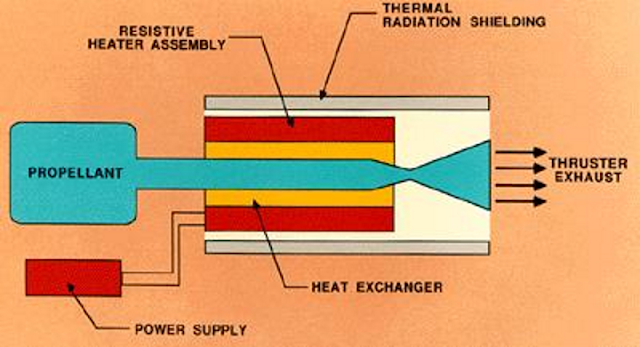 Tungsten can handle temperatures as high as 3500K. This is usually higher than the temperatures of the nuclear cores themselves, as they are under other design constraints (such as surviving the intense radiation).If we employ a resistojet as the electrical booster to a ‘modern’ nuclear thermal rocket, we can raise the temperature of the exhaust from 2800K to 3500K. This might seem like a minor increase, but there is a significant benefit that comes with hydrogen propellant thermally decomposing into individual atoms (H2 to H). This halves the average molar mass of the exhaust, meaning that Isp increases from 912s (8.94km/s) to 1270s (12.4km/s).For an advanced nuclear core already operating at 3200K, the benefit is so minor as to be negligible since it has already thermally decomposed the hydrogen and would only receive an Isp increase from 1213s (11.9km/s) to 1270s (12.4km/s).Efficiency is said to be about 80%.ArcjetAn arcjet heats up propellant to very high temperatures using electric arcs. It is not limited by the melting point of any material, but it does suffer from constant erosion of its electrodes.
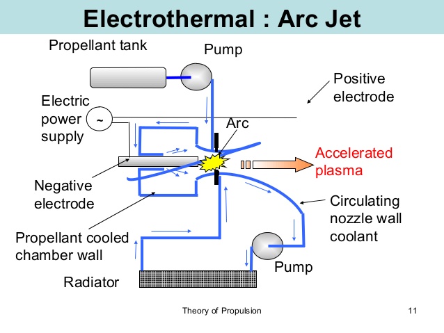 Temperatures as high as 12,000K are achievable, and since the exhaust gases have already been heated up by a nuclear reactor, we can dismiss ionization losses and only look at the 80-90% thermal efficiency.
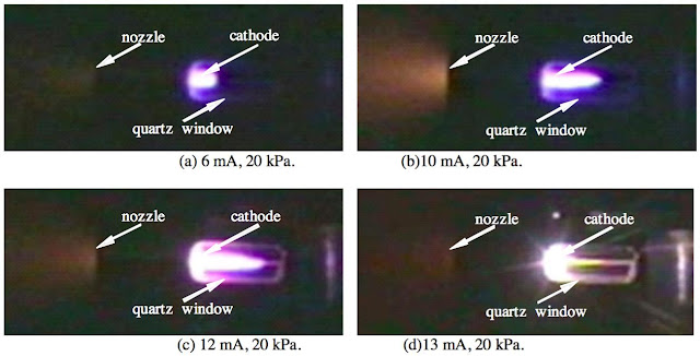 In this electric booster, we are not temperature limited but energy limited.
Any propellant entering the electrical booster should be considered a plasma (or soon will be!). This means that it has a heat capacity ratio of 1.66 and a fixed heat capacity of 20.37J/mol/K.In practical terms, it takes 20.37kJ to heat up 1kg of monoatomic hydrogen by 1 Kelvin, and 6.36kJ to heat up 1kg of methane thermally decomposed into its constituents (average molar mass 3.2g/mol) by 1 Kelvin.If we have 6MJ available for each kg of hydrogen propellant, we can increase the temperature by 265K (assuming 90% efficiency) from 3200K to 3465K, with a corresponding increase in exhaust velocity of just 4%.Those same 6MJ delivered to an arcjet running on methane would increase temperature by 849K from 3200K to 4049K, increasing exhaust velocity 12.4%...Microwave, Laser and RF Induction heatingThese are improved methods for further heating propellant.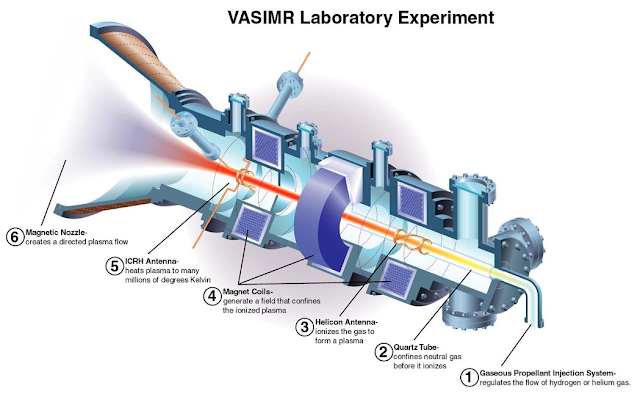 Microwaves or lasers can be used to directly heat propellant, with the choice being made depending on how well their wavelengths are absorbed.RF Induction uses an alternating magnetic field to act on a conductive propellant.Efficiency with these methods can be good (>60% efficiency lasers) to great (>90% efficient induction coils) and they have no temperature limits. Erosion is not a problem, so they can operate for a very long time. Power density is also improving every year.
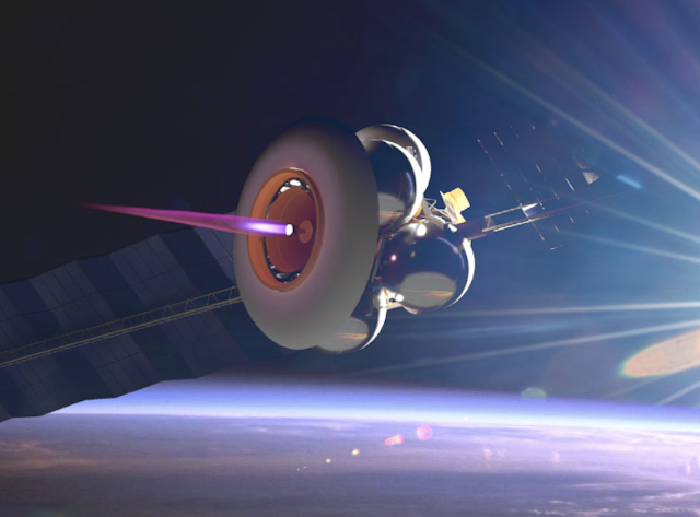
Unlike resistojets or arcjets, there are no practical temperature limits, only the heat flux that the walls can handle.Electromagnetic accelerationThis category of electric booster uses electromagnetic forces to directly accelerate the propellant using Lorentz, Hall or Ponderomotive effects. More electrical energy directly becomes kinetic energy, making them much more effective than simply heating the propellant.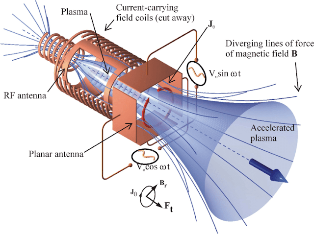 We are interested in electrodeless plasma thrusters. Because the source of our plasma is a nuclear reactor core emitting very high temperature gases, to which an easily ionized seeding material can be added, we will not have to suffer the losses from using equipment required to generate plasma. That already significantly improves our potential efficiency.
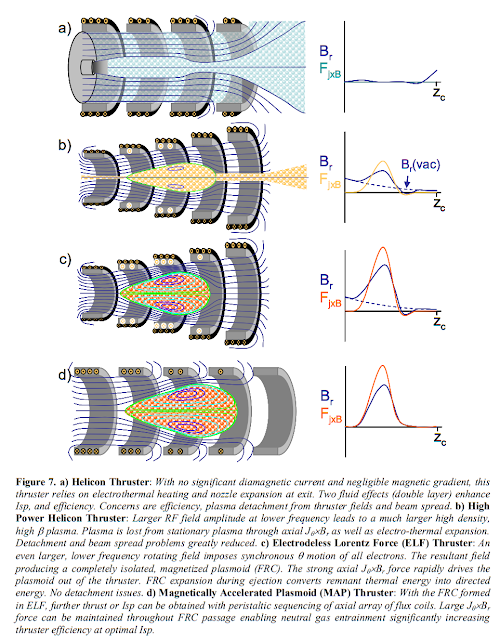 Some of the simpler designs, like a Pulsed Inductive Thruster, are unusable as the propellant from the reactor is continuous.Others like the ponderomotive plasma engine, based on the non-heating part of the VASIMR engine, the travelling wave plasma accelerator or an ELF design can directly convert electricity into kinetic motion with efficiencies exceeding 80% using a variety of propellants and have practically unlimited exhaust velocity (the VASIMR in high gear is supposed to reach an Isp of 30,000s!).
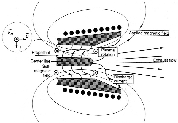 The use of superconducting magnets can bring the power density of the electrical booster to acceptable levels, so they do not affect propulsion mass requirements too much. Even better, they do not significantly increase the temperature of the exhaust, so they can operate for much longer with lighter materials.
A highly efficient power generating cycle using all the tricks in the book (recirculating, combined cycles, regeneration and so on) using these types of accelerator could push Isp up to 1800s.
Use of radiatorsUsing cryogenic propellant as a heatsink does not mean that radiators must be excluded from designs that can use them.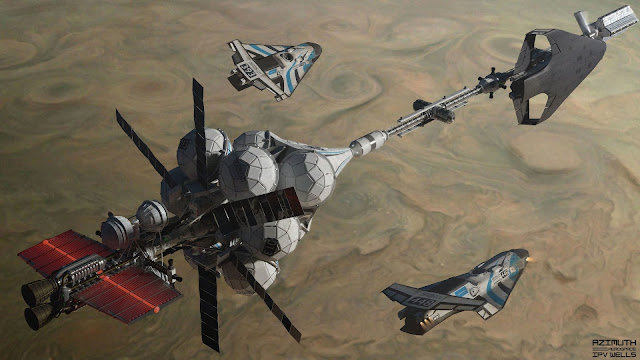 Power generating cycles with higher temperature cold ends can radiate a lot of their waste heat away using relatively small radiators. Each 1m^2 of double-sided fins exposed to space can remove 7kW of waste heat when radiating at 500K, and 113.4kW at 1000K. Other radiator types can handle this waste heat with very little equipment mass, by spraying liquid droplets or electrostatically cycling dust in and out of a heat exchanger.Therefore, we can have power generating cycles that use radiators in addition to the cooling capacity of propellant to extract even more electricity from each kilogram consumed. Every MJ removed using radiators is a MJ that doesn’t using up the propellant’s cooling capacity.For example, in the modern thermionic converter design, the collector plate is to be held at 1000K. Each kg of liquid hydrogen used to cool it can absorb 14.2MJ, so 1 kg/s of that propellant flow can be replaced by 125m^2 of double-sided fins removing 113.4 kW/m^2.A spaceship can use radiators to increase the total amount of electrical power it produces or reduce the rate at which propellant is consumed. Radiators can be extended or retracted to change the power output or rate of propellant consumption, which is a nice option to have when facing different situations such as combat (where radiators could be damaged) or prolonged accelerations (where a maximally efficient electric engine is preferred).Power generating systems that can operate at different temperatures give even more options. Small radiators can be used to handle high temperature heat (like a thermionic converter operating between 2000 and 1500K) while lower temperature steps that would require heavy thermal management could instead use a flow of cryogenic propellant. When radiators need to be retracted, propellant handles all cooling requirements. If the extra power is not needed, the power generating cycle only works with the high temperature steps and cuts off the lower temperature ones.
 Impact of the technologyTwo types of spacecraft benefit the most from Nuclear Thermal-Electric propulsion technology.The first are rapid transports that wish to minimize interplanetary travel times. The second are warships.
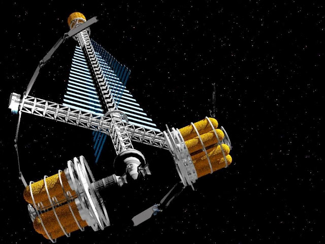 Rapid transports aim to travel along very energetic trajectories using a lot of deltaV. They want the rapid acceleration of nuclear thermal propulsion but also the Isp of nuclear electric propulsion.Rapid acceleration is needed to escape low orbits near planets quickly, both maximizing the Oberth effect and reducing the amount of time spent traversing radiation belts. High thrust chemical engines are why Apollo missions could get to the Moon in 3 days at the cost of 4km/s of deltaV, but a proposed electrical propulsion system would take 9 months to slowly spiral its way there.A nuclear thermal rocket can deliver this high thrust as well as double the specific impulse. With the thermal-electric design boosting Isp from around 1000s to nearly 2000s, the deltaV capacity is doubled again without losing much acceleration.This NASA document describes how a spaceship with both high thrust and high Isp propulsion options ends up having better performance than either option alone. NTER can realize that ideal.Warships benefit even more from nuclear thermal-electric propulsion.It would have three competing requirements. The first is to generate electrical power so that it can use lasers, electromagnetic accelerators, active sensors and other energy-intensive equipment. The second is to protect itself from enemy fire. The third is to keep up with its targets and run away from missiles.The first two requirements are in conflict with each other because generating electricity also produces waste heat, and getting rid of waste heat generally means exposing large radiator panels to space. These panels cannot be armored (it would defeat their function) and so become large weakspots that when damaged, prevent electricity from being generated.The second and third requirements clash because deltaV needs must be met by large propellant reserves. The best propellants, like liquid hydrogen, are very voluminous and covering propellant tanks with armor becomes a massive penalty. An opponent can bring more weapons to the fight if they do not have the same mass penalty, while you would be completely at the mercy of missiles and kinetics if you cannot maneuver out of the way if you did not protect your propellant tanks.
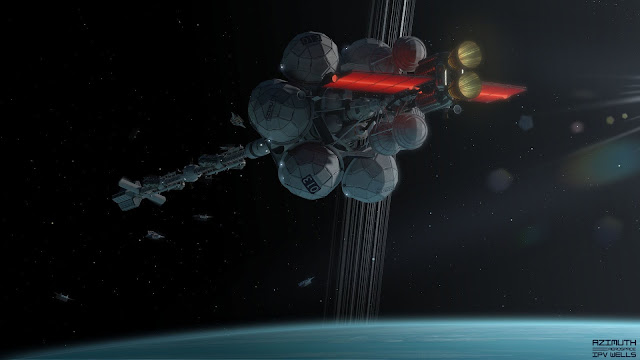 All of these competing requirements can be met by a NTER.By using propellant as a heatsink, electricity can be generated while radiators are retracted or not even part of the design. This means a fully armored spaceship with no weakspots can still generate the megawatts it needs to win a fight. Furthermore, the electrical output can be used to increase the exhaust velocity of denser, less optimal propellants like liquid methane. It is 6.7 times denser than liquid hydrogen, so the volume of propellant tanks for a given mass ratio is correspondingly smaller. Less armor is needed.
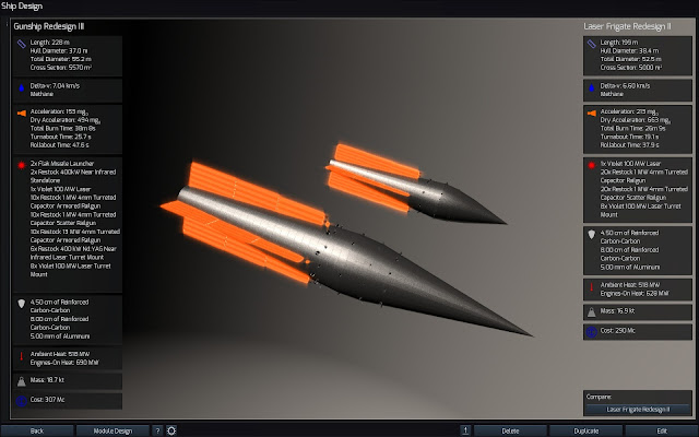 A warship using NTERs can eventually outrun spaceships using NTRs and outmatch spaceships using NERs in both protection and acceleration.
From a science fiction perspective, it can allow for an argument to be made as to why there are no visible radiators. NTER propulsion means that we can consider 'softer sci-fi' designs as valid from a scientific standpoint.
You do not have to compromise between realism considerations and your choice of spaceship 'look'.


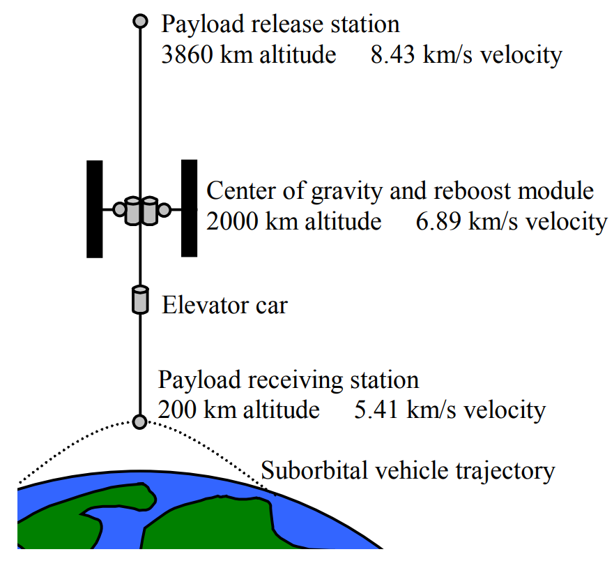


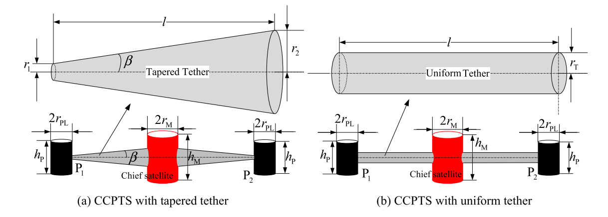
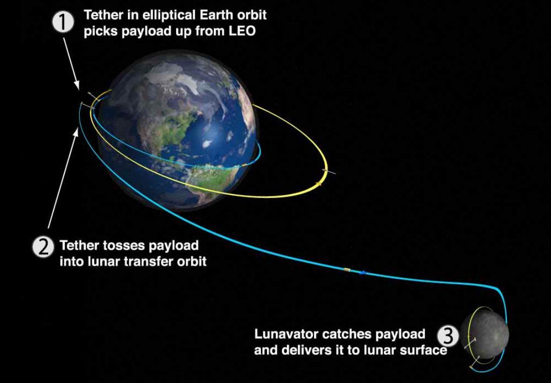

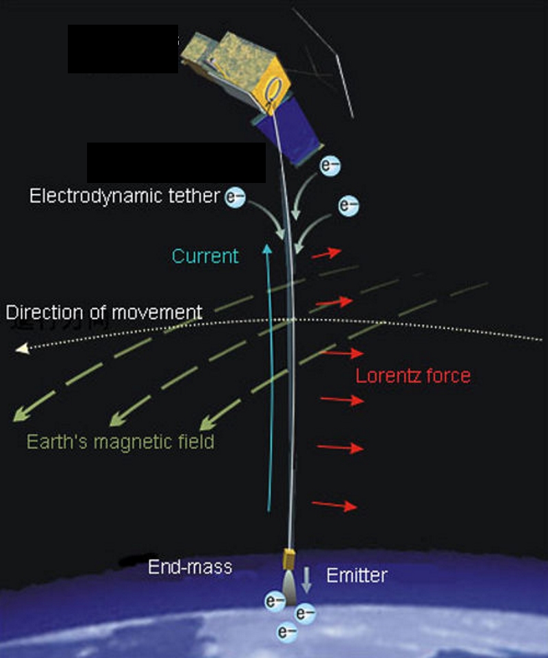
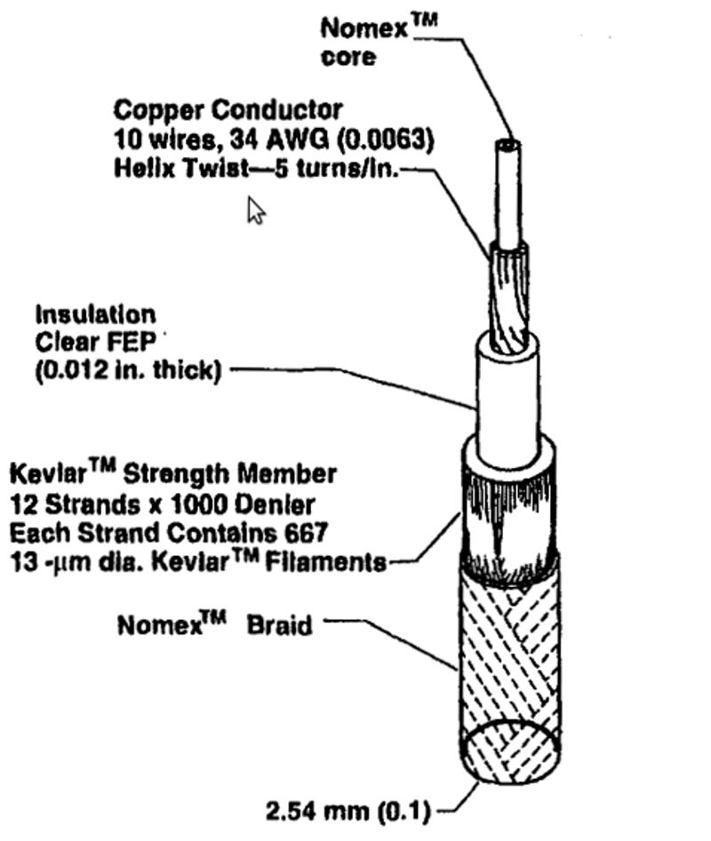

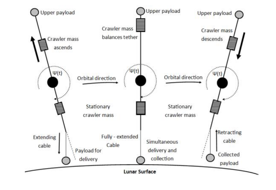
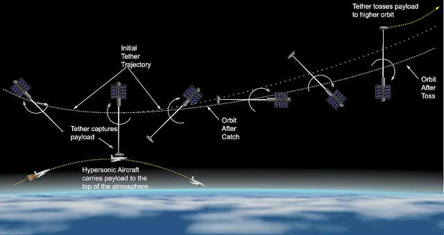
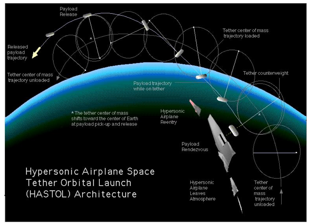

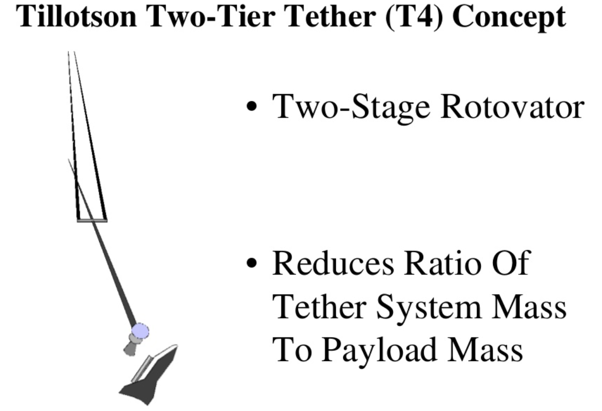


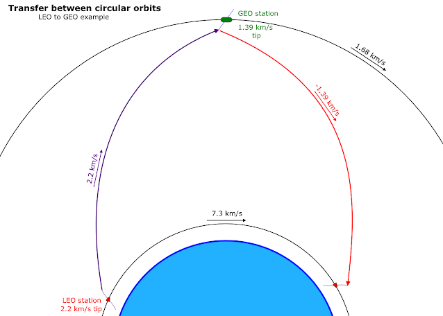
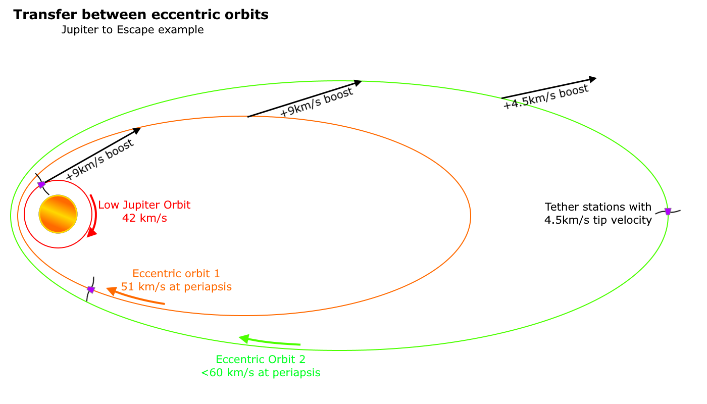
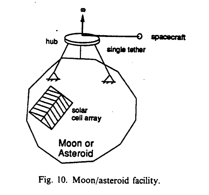


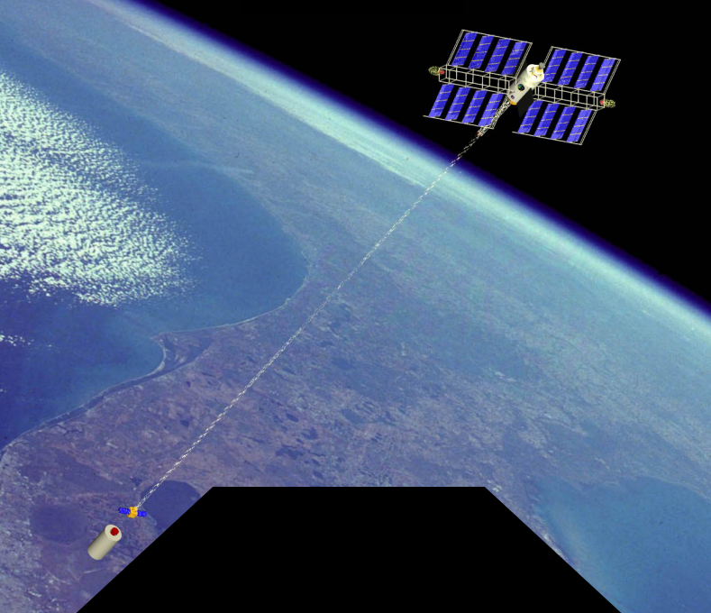


")


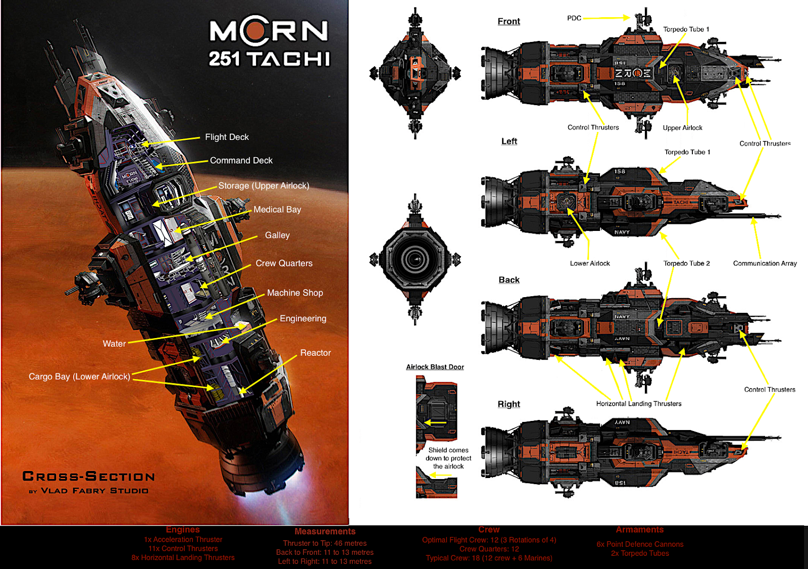


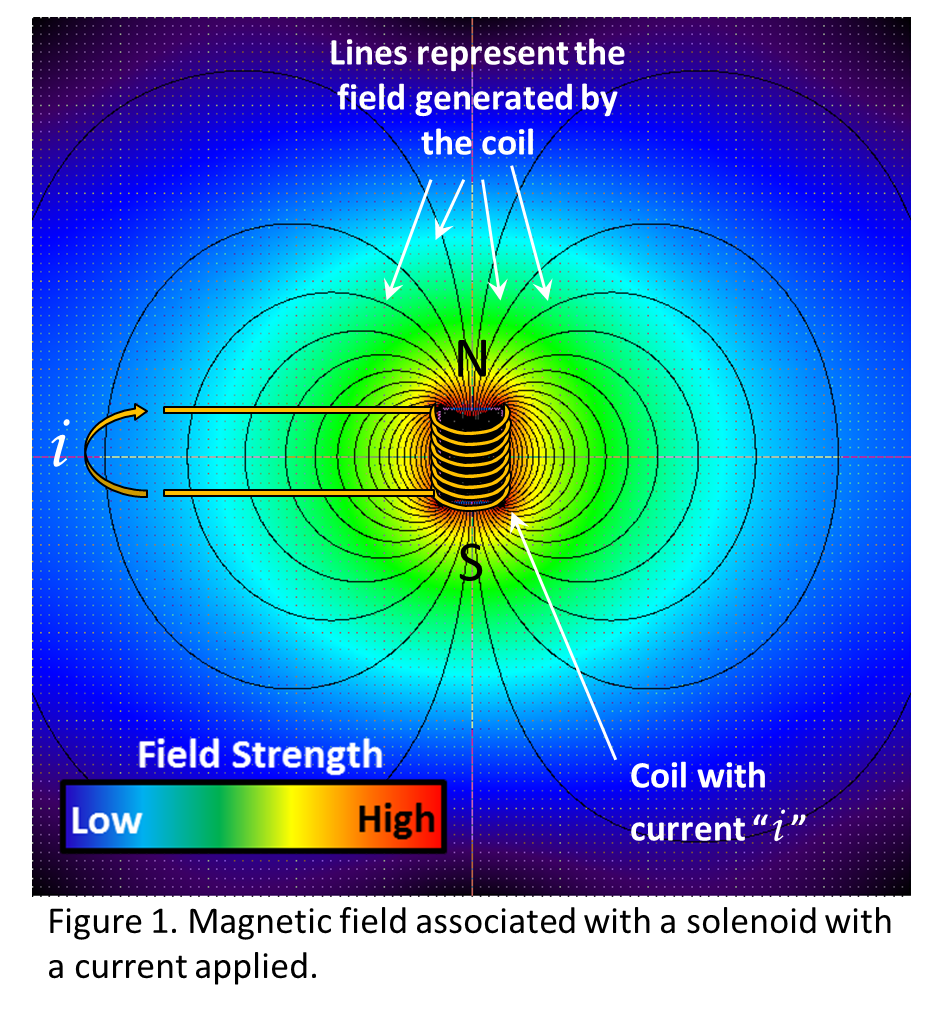


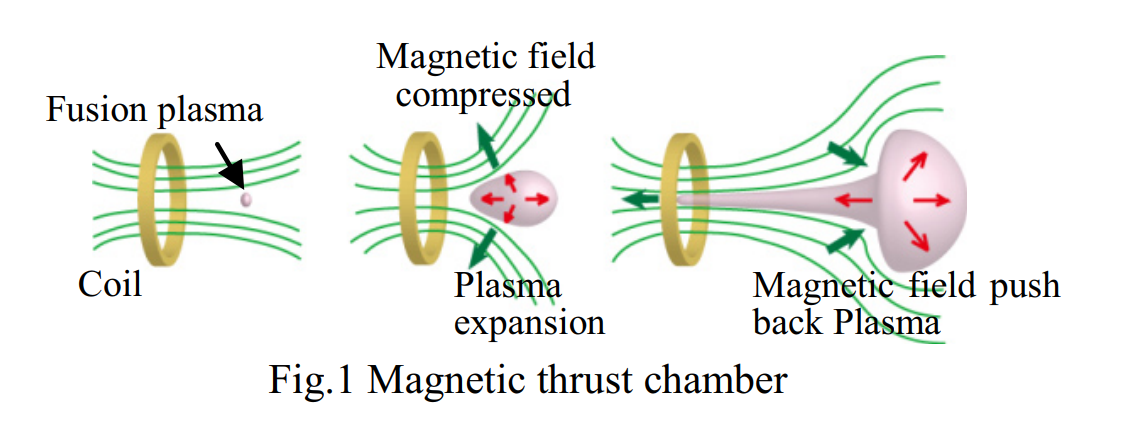


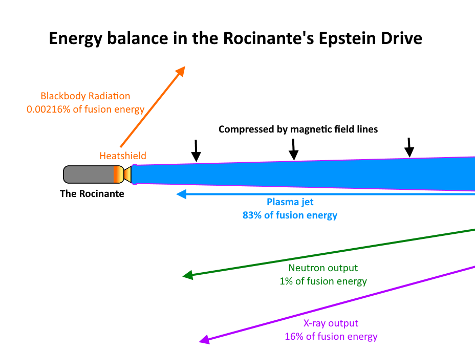


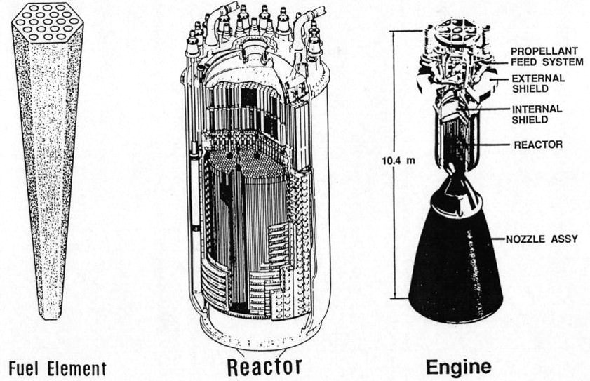


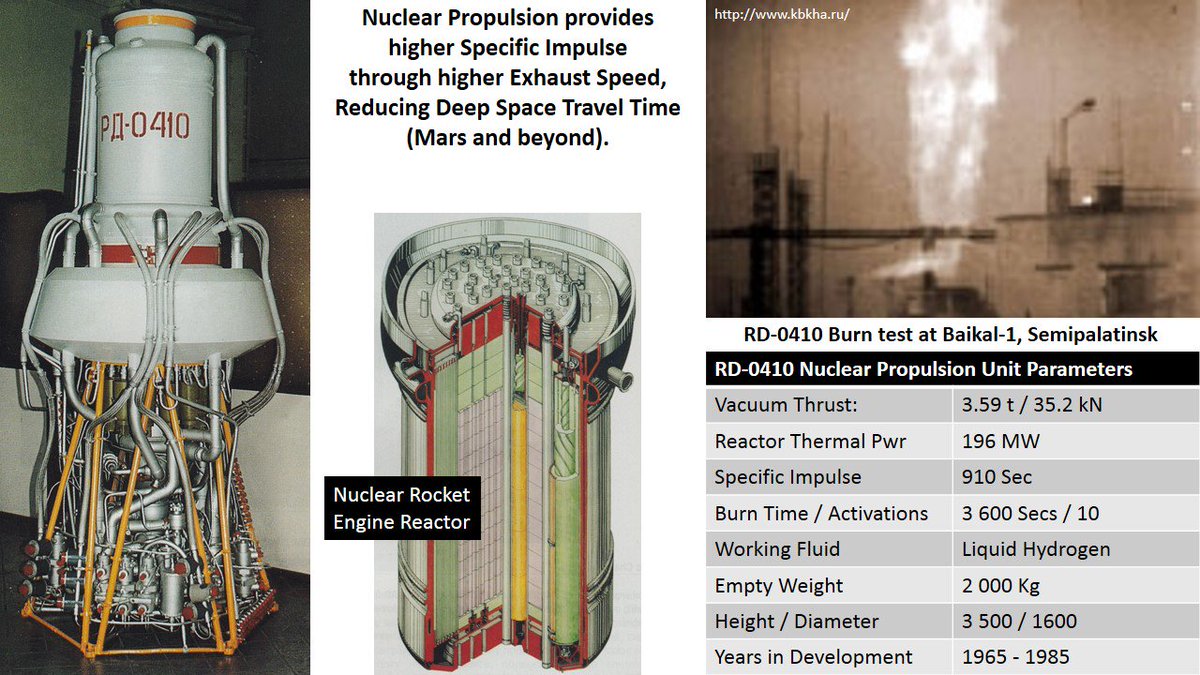
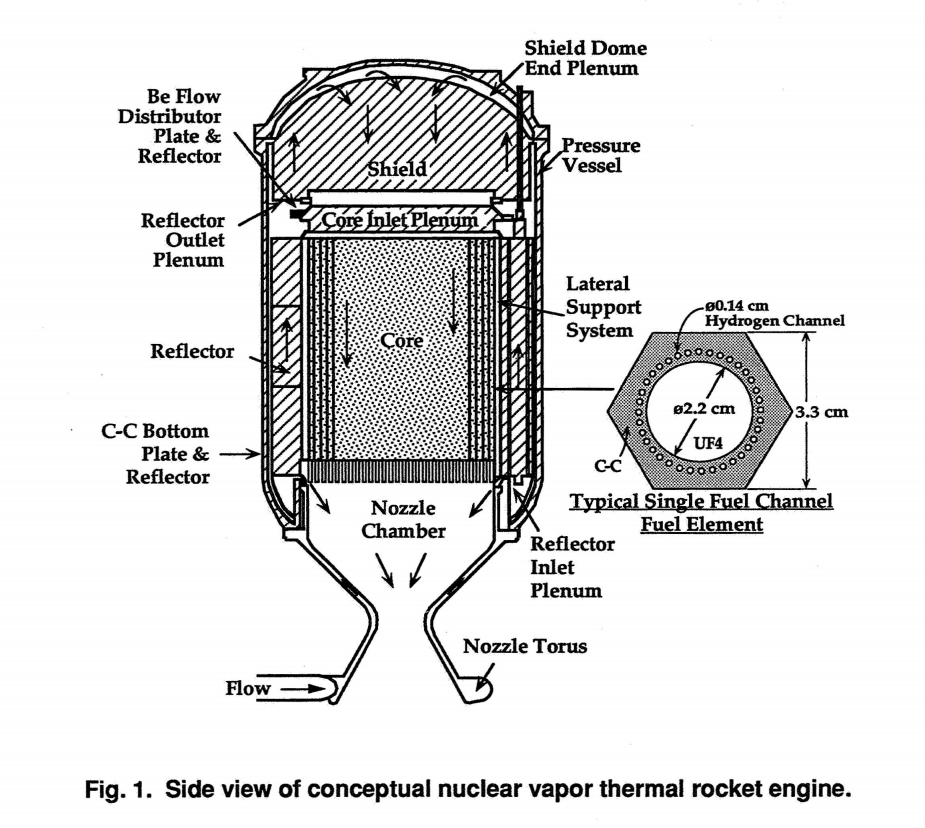
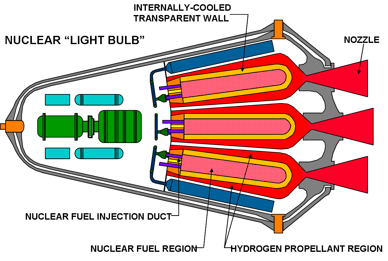
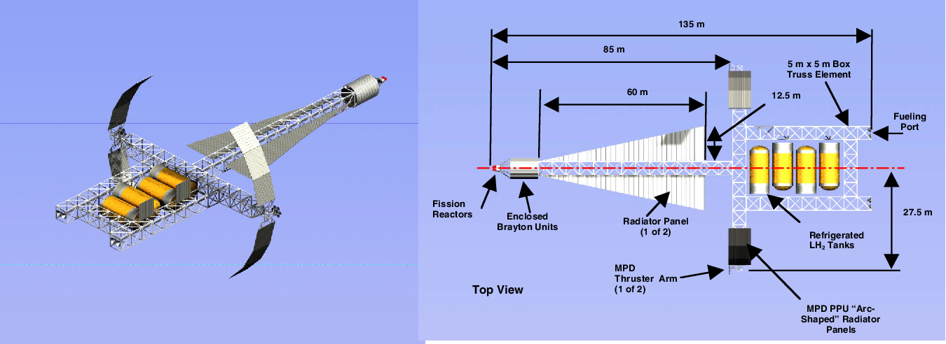


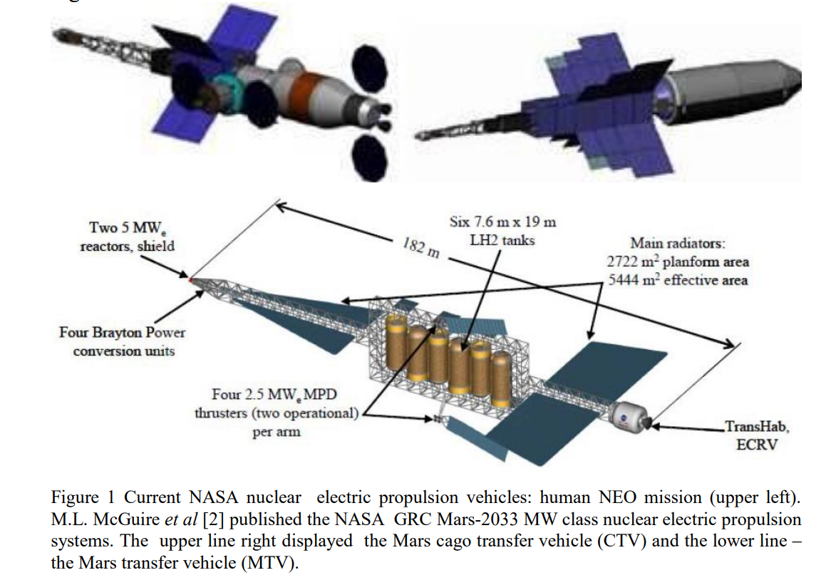


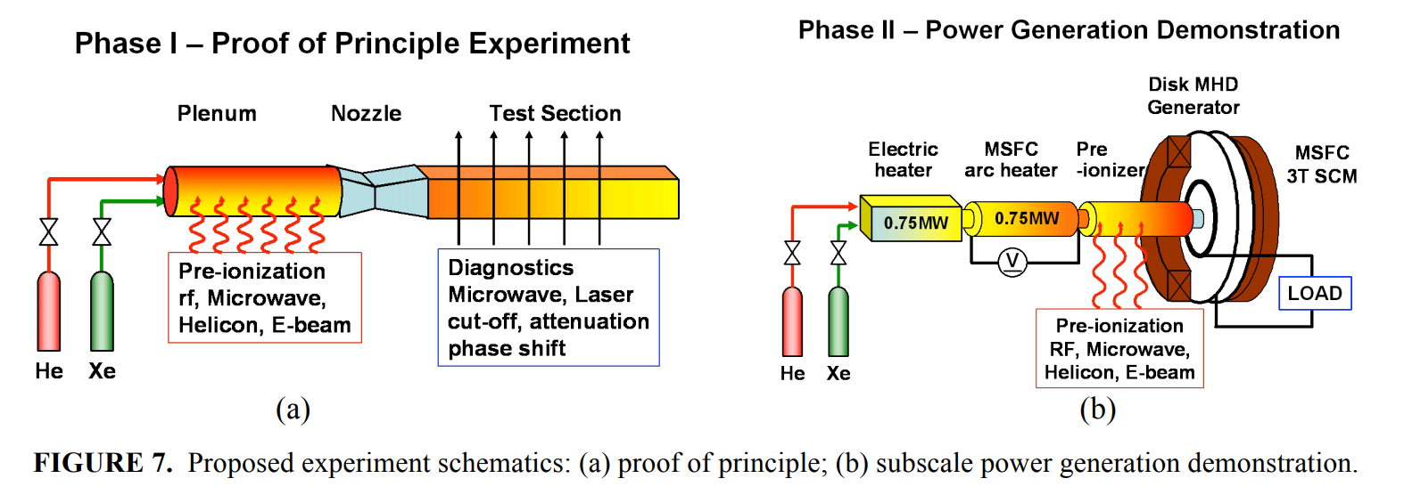

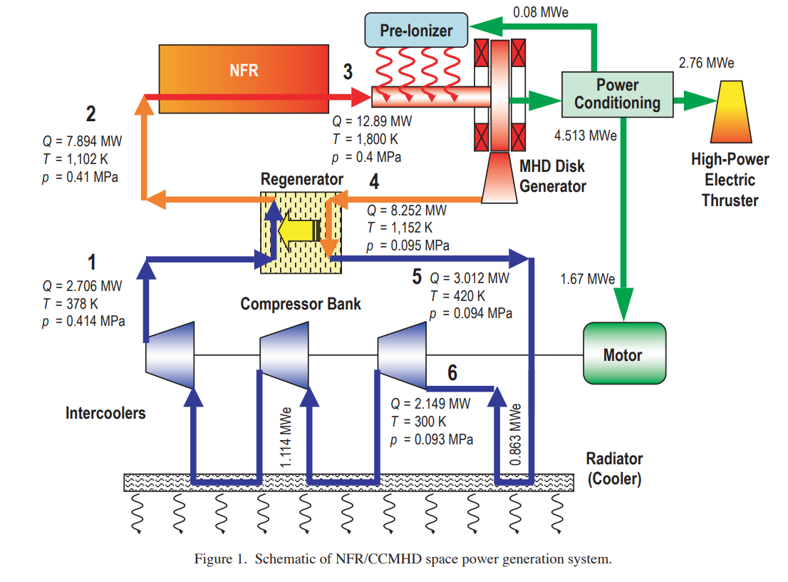


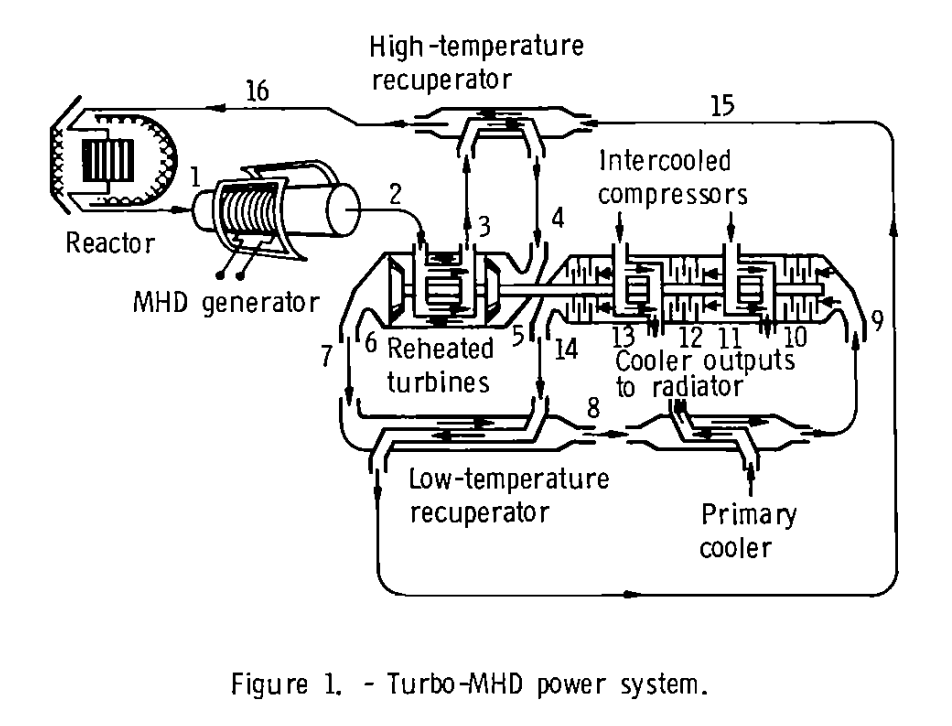


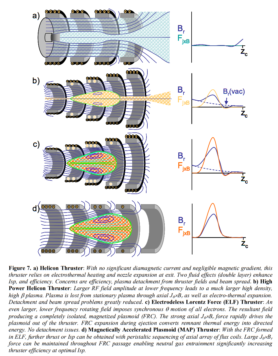


Nuclear Photon Rockets: Flashlights to the Stars
in Science & Spaceflight
Posted
This is the most recent post on ToughSF: http://toughsf.blogspot.com/2020/11/nuclear-photon-rockets-flashlights-to.html
Nuclear Photon Rockets: Flashlights to the Stars
The interstellar challenge